Continue to Site

Welcome to EDAboard.com

Welcome to our site! EDAboard.com is an international Electronics Discussion Forum focused on EDA software, circuits, schematics, books, theory, papers, asic, pld, 8051, DSP, Network, RF, Analog Design, PCB, Service Manuals... and a whole lot more! To participate you need to register. Registration is free. Click here to register now.

Motor speed detect sensor

Status
Not open for further replies.

vikash23

Full Member level 2
Joined
Jul 31, 2012
Messages
133
Helped
3
Reputation
6
Reaction score
3
Trophy points
1,298
Activity points
2,676
Hi,

I am using a motor that spins at 6000 rpm.

I would like to connect a sensor to the shaft of the motor to test the speed of the motor .

The output of the sensor can be analog or digital.

Low cost sensors that I have seen is capable of measuring only upto 5000rpm.

Can any one please suggest me a sensor module that can perform my requirement.

The working voltage of the sensor. can be upto 24V.

I know i can measure the rpm by using the back emf but I need to measure using the sensor and compare the value with the back emf value.

Thanks.
 

Hi,

from the RC it should be able to measure RPM up to 30,000. or sth in this range.

Klaus
 
Hi

I am looking for something like this

https://www.electroschematics.com/12275/motor-speed-sensor-module-circuit/.

What I am not sure is , upto what rpm can this measure ?

The circuit has a couple of mistakes;
for starters, the comparator IS NOT set up as a Schmitt trigger, as it lacks positive feedback, and thus is sensitive to noise.
Whoever designed this circuit noticed this noise sensitivity, and added a 100n capacitor (which would make the risetime slower) and limit the maximum frequency.

Lastly, it offers the following statement: The last 10K resistor (R7) is an optional pull-up resistor.
No, it is not optional. It is true that R6 and LED2 do pull up the signal, but because of the LED's forward voltage drop, it won't pull it all the way to 5 volt.
 
Hi

how about the below module?

**broken link removed**

Can I able to achieve 6000rpm ?

Regards,
Vikash
 

These cheap modules do not provide any meaningful specifications.
I mean, who cares if the module weighs 3 or 4 grams?

But actual design specs, like the maximum count frequency, are sorely lacking. Most likely because the poor performance.

6000RPM equals 200 Hz, with a two slot wheel (bare minimum). It is a relatively slow frequency. It may work.

Eventually, you will have to make a decision, purchase one and test it yourself. There is no other way to answer your question.
 

Hi,

is there any technical description? If not - how do you think one of us can answer your question?

Klaus
 

You might be able to use a frequency counter and
a bit of arithmetic, picking off the armature voltage
spikes from commutation via a blocking cap (if the
spikes are large enough for the frequency counter
to "see").

How many spikes per revolution, you'd have to
measure or deduce.
 

Hi,

is there any technical description? If not - how do you think one of us can answer your question?

Klaus

I am trying to implement a test rig to test my pump.

The pump runs with CAN bus where it spits out the speed of the pump.

but externally i need to connect the speed sensor to measure the speed and compare the value with the CAN bus values and prove both are same. There might be a 10% deviation int he speed.

The max speed of the pump is 6000rpm.

The pump voltage is 32V max.

I would like to in interface the sensor output with Labview and see the speed values in the labview software.

https://uk.farnell.com/honeywell/sng-qpmb-000/quadrature-speed-direction-sensor/dp/2773612

The above model looks it will satisfy my requirement and and it had a wide frequency range of 3Hz to 20KHz. 24V max input voltage.
 

What you are showing is a reluctance sensor.
It only works if you have a toothed wheel with the dimensions shown on table 2.

- - - Updated - - -

I'm going to show you a project which I finished last month, and works very nice.

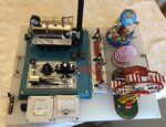
I have a Wilesco Steam Engine kit with an attached generator (which powers some lights) and a power take off to drive accessories. See the image.

I wanted to read the generator voltage and the the RPM, to add a nice touch. I wanted to keep the vintage look, so the voltmeter is analog.

The voltmeter was simple, just add one in parallel with the generator output.
For the tachometer, I added 10 white stripes to the black flywheel. Close to it I placed a photo-reflective sensor.

The attached schematic are the electronics. Since I wanted to keep the look vintage with an analog meter, I used a frequency to current converter with a LM331. But the part that interests to you is how I clamp the phototransistor's output to one Vbe via the 2N3904.
This is the crucial part....phototransistors have lots of base capacitance which limit the maximum pulse frequency. With this arrangement, I could go as high as 1000 Hz (close to 6000 RPM with 10 slots) with a nice squarewave at the collector.

Just omit the whole LM331 circuit and thake the output from the 2n3904 collector.

schematic.png
IMG_0014.JPG
 
Status
Not open for further replies.

Part and Inventory Search

Welcome to EDABoard.com

Sponsor

Back
Top