Welcome to our site! EDAboard.com is an international Electronics Discussion Forum focused on EDA software, circuits, schematics, books, theory, papers, asic, pld, 8051, DSP, Network, RF, Analog Design, PCB, Service Manuals... and a whole lot more! To participate you need to register. Registration is free. Click here to register now.
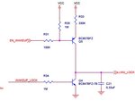
above given circuit Transistor Q5 is not on properly for base will be drive in controller , given is vcc=3V
any can sage me why this is not operated properly
Apart of the issue not being clear at all, the 100K/1M biasing resistors seems very high to operate with a 3,3v VCC. I would consider at a first approximation, thinking about to scale them at a 1/10 ratio.
hii
1/10 ratios apply 1000000/100000=10 this is right but in EN_WAKEUP signal digital scope is connected then this is wark properly ... prob is remove then this is not work proper
Still not clear, anyway...In my student time, always before assembling some experiment in electronics lab, I did simulations on SPICE by writing the whole circuit netlist in text file, in order to adjust the polarization values precisely to meet what I wanted from the circuit. Luckily, there is available LTspice that you can download for free and quickly mount that simple circuit, and if I'm not wrong, both the above transistors are there on its library. In short, do not waste time anymore mounting circuits for which you have not made precise calculations. Find the values in the simulation first. Tip: Perform separate tests with the top and bottom transistors, either replacing one or the other with a resistor.
This site uses cookies to help personalise content, tailor your experience and to keep you logged in if you register.
By continuing to use this site, you are consenting to our use of cookies.