Continue to Site

Welcome to EDAboard.com

Welcome to our site! EDAboard.com is an international Electronics Discussion Forum focused on EDA software, circuits, schematics, books, theory, papers, asic, pld, 8051, DSP, Network, RF, Analog Design, PCB, Service Manuals... and a whole lot more! To participate you need to register. Registration is free. Click here to register now.

Phase Noise Simulation of Injection Locked Frequency Multiplier

Status
Not open for further replies.

Hamed94

Junior Member level 1
Joined
Apr 19, 2017
Messages
18
Helped
0
Reputation
0
Reaction score
0
Trophy points
1
Activity points
172
Hi,

I have designed a mm-wave injection-locked frequency multiplier (or sub-harmonic injection-locked oscillator). My problem is that I don't know how to simulate its output phase noise. When I use simple HB simulation in ADS (Advanced Design System) or PSS simulation in Cadence, I get wrong results. I know that the output phase noise must be 20*logN dB higher than input's one where N is multiplication factor. Using Envelope simulation in ADS, I see that output is locked to the input's Nth harmonic.

Could you please help me to simulate output phase noise either in ADS or Cadence?
Any references or tutorials would be appreciated too.

Sincerely
HF
 

Show us your situations in detail.

This is my whole system. I have designed a low phase noise oscillator at 1.875 GHz as the reference. I want to inject its 16th harmonic to another oscillator at 30 GHz. In order to increase its harmonic contents, I've used CMOS gates as pulse generator circuit.
In HB simulation in ADS, I set fundamental frequency to 30 GHz and enable oscillator analysis and specify 30 GHz osillator output nodes as oscillator nodes.
Untitled.jpg
 

In HB simulation in ADS, I set fundamental frequency to 30 GHz
Wrong.
Fudamental frequency has to be 1.875GHz.
Here you have to set enough large Max Order such as 16*10=160.

Shooting-Newton-PSS might be efficient than HB-PSS.
However Shooting-Newton-PSS is not available in ADS.

and enable oscillator analysis
Wrong.
You have to do driven HB analysis not Autonomous HB analysis.

See https://www.edaboard.com/showthread.php?t=345800#6
 
Last edited:
How?

How should I configure HB simulation? Just setting fundamental frequency to 1.875 GHz? Is that enough?
How should I specify oscillators node? 1.875 GHz one or 30 GHz one?
 

How should I configure HB simulation?
Show me ADS netlist.
Circuit descriptions are not needed.

Just setting fundamental frequency to 1.875 GHz?
Is that enough?
You have to set enough large Max Order such as 10*(30G/1.875G)=160.

Shooting-Newton-PSS might be efficient than HB-PSS, since required orders are large.
However Shooting-Newton-PSS is not available in ADS.
Only HB-PSS is available in ADS.

See https://www.edaboard.com/showthread.php?t=195061#3

How should I specify oscillators node?
Still you can not understand HB analysis at all.

Injection locked oscillator is not autonomous circuit.
So you must not do Autonomous-HB Analysis.

See https://www.designers-guide.org/Forum/YaBB.pl?num=1511260500

Is your 1.875GHz block is an autonomous circuit in your simulation ?
 
Last edited:
Yes, It is an autonomous circuit.
Here is my netlist :

Code:
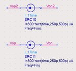
Noisecon:NC6 InputFreq=noisefreq NoiseFreqPlan="NC6_nl_stim" CarrierIndex[1]=16 \
PhaseNoise=1 NoiseNode[1]="Vop2 Von2" SortNoise=1 \
NoiseThresh=30 IncludePortNoise=yes \
BandwidthForNoise=1.0 Hz 
                        SweepPlan: NC6_nl_stim Start=10 Hz Stop=100 MHz Dec=20 
                        

Fosc=29.771651 GHz
Finj=Fosc/16

Noisecon:NC5 NoiseFreqPlan="NC5_nl_stim" CarrierFreq=Finj \
PhaseNoise=1 NoiseNode[1]="Vop Von" SortNoise=0 \
IncludePortNoise=yes \
BandwidthForNoise=1.0 Hz 
                        SweepPlan: NC5_nl_stim Start=10 Hz Stop=100 MHz Dec=20 
                        

HB:HB6 MaxOrder=4 Freq[1]=Finj Order[1]=200 StatusLevel=2 Restart=no OutputBudgetIV=no OutputPlan="HB6_Output" Noisecon[1]="NC6" Noisecon[2]="NC5" 

OutputPlan:HB6_Output \
      Type="Output" \
      UseNodeNestLevel=yes \
      NodeNestLevel=2 \
      UseEquationNestLevel=yes \
      EquationNestLevel=2 \
      UseSavedEquationNestLevel=yes \
      SavedEquationNestLevel=2 \
      UseDeviceCurrentNestLevel=no \
      DeviceCurrentNestLevel=0 \
      DeviceCurrentDeviceType="All" \
      DeviceCurrentSymSyntax=yes \
      UseCurrentNestLevel=yes \
      CurrentNestLevel=999 \
      UseDeviceVoltageNestLevel=no \
      DeviceVoltageNestLevel=0 \
      DeviceVoltageDeviceType="All"

Tran:HB6_tran HB_Sol=1 SteadyState=1 StatusLevel=3 \
Freq[1]=Finj Order[1]=200 

Component:tahb_HB6 Module="ATAHB" Type="ModelExtractor" \ 
 Tran_Analysis="HB6_tran" HB_Analysis="HB6"
 
Last edited by a moderator:

It is an autonomous circuit.
I disabled oscillator analysis in HB simulation and set its order to 200, but my problem still exists.
Here's my netlist.
Have I configured noise analysis correctly?Capture.JPG
 

It is an autonomous circuit.
I disabled oscillator analysis in HB simulation
and set its order to 200,
but my problem still exists.
Show me time waveforms and Spectrum for output nodes of 1.875GHz and 30GHz.

If your circuit is truely autonomous, HB can not converge with "disabled oscillator analysis".

And show me logfile of ADS.

NoiseNode[1]="Vop Von" : 1.875GHz ?
NoiseNode[1]="Vop2 Von2" : 30GHz ?

Show me noise analysis results.
 
Last edited:
Show me time waveforms and Spectrum for output nodes of 1.875GHz and 30GHz.
Time domain waveforms:
Capture.JPG
Frequency domain waveforms (or spectrums):
Capture2.JPG
So, I noticed that amplitudes in the time domain and frequency domain do not match.
Maybe it is because of using these source in schematics:
Capture3.JPG
I placed these sources to force oscillators to start up and ofter 500ps their effect goes away. (Without using these sources, oscillations will not start up in transient analysis.)
Next time, I opened these sources for HB simulation. Oscillator analysis is disabled in HB simulation.
The spectrums:
Capture4.JPG
As you see, amplitudes are almost zero.
Next time I enabled oscillator analysis and chose 1.875GHz oscillator nodes for this purpose.
The spectrums:
Capture5.JPG
The amplitude for the 1.875GHz oscillator is almost correct but for 30GHz one is wrong.
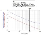
Phase noise curves for 1.875GHz oscillator relative to 1.875GHz frequency and for 30GHz oscillator relative to 30GHz frequency is shown below:
Capture6.JPG
As you see, output phase noise is almost 20log16=24 dB higher than input phase noise as expected. (Input phase noise shown in this figure is correct. because when I simulate the 1.875GHz oscillator in isolation, I get the same result for phase noise.)
However, I can't trust this result because oscillation amplitude shown in last HB simulation is wrong. What do you think? Is the phase noise result correct?
 
Last edited:

Next time I enabled oscillator analysis
and chose 1.875GHz oscillator nodes for this purpose.
I confirmed your 1.875GHz block is an autonomous circuit.

The amplitude for the 1.875GHz oscillator is almost correct but for 30GHz one is wrong.
You plot HB.Vop2-HB.Von2.
So even order harmonics are suppressed.

Show me plot of ts(HB.Vop2-HB.Von2), dB(HB.Vop2-HB.Von2), dB(HB.Vop2) and dB(HB.Von2).

However, I can't trust this result
because oscillation amplitude shown in last HB simulation is wrong.
What do you think?
Is the phase noise result correct?
I think it is correct.
 
Last edited:
Show me plot of ts(HB.Vop2-HB.Von2), dB(HB.Vop2-HB.Von2), dB(HB.Vop2) and dB(HB.Von2).

ts(HB.Vop2-HB.Von2) and dB(HB.Vop2-HB.Von2):

Capture8.JPG

dB(HB.Vop2) and dB(HB.Von2) :

Capture9.JPG

Why is the time domain waveform of 30GHz oscillator not a sinusoidal?
 

Next time I enabled oscillator analysis
and chose 1.875GHz oscillator nodes for this purpose.
Choose 30GHz nodes as oscillation nodes.

Show me plot of ts(HB.Vop2), ts(HB.Von2) and ts(HB.Vop2-HB.Von2).
 
Choose 30GHz nodes as oscillation nodes.

Show me plot of ts(HB.Vop2), ts(HB.Von2) and ts(HB.Vop2-HB.Von2).

Sorry for the delay. In this case, the oscillator analysis does not converge.
This is the log file:


Warning detected by hpeesofsim in frequency search during HB analysis `HB1'.
Circuit is stable. No zero phase crossings of the injected current were
found. For oscillation, a negative going zero phase crossing should exist.
Will try fixed frequency amplitude search.
Error detected by hpeesofsim in arc-length continuation during HB analysis `HB1'.
Value of `HB1_OP.V' went out of range during arc-length continuation.
The range is -999.998 V to 2 kV.
Convergence hints:
o Expand the range with ArcMinValue and ArcMaxValue and re-simulate.
Warning detected by hpeesofsim during HB analysis `HB1'.
Oscillator analysis did not converge. Setting solution to zero.
Warning detected by hpeesofsim during HB analysis `HB1'.
More than one mixing term has landed on frequency 0 Hz.

And the time domain waveforms:
Capture10.JPG

As a conclusion, I think the method that you said for phase noise simulation (HB simulation with 1.875GHz as the fundamental frequency, with a large number of harmonics, enabling oscillator analysis and choosing 1.875GHz oscillator nodes for this purpose) is correct. Because its phase noise results, are as expected. Besides, when I asked one of the authers of a paper with the same topic, he told me the same approach. (However in Cadence and with PSS and PNOISE simulation)

Thank you for all your help.

Regards,
HF
 

In this case, the oscillator analysis does not converge.
Set "Harm=16".
Code:
OscProbe:HB1_OP Node[1]="Vop2" Node[2]="Von2" FundIndex=1 Harm=16 NumOctaves=8 Steps=100

Besides, when I asked one of the authers of a paper with the same topic,
he told me the same approach.
(However in Cadence and with PSS and PNOISE simulation)
Which algorithm does he use as PSS, Shooting-Newton or HB ?
 
Last edited:
Set "Harm=16".

Still not convergence:


Warning detected by hpeesofsim during TRAN analysis `HB1_tran'.
Component `L1.Z1':
No ImpMaxFreq is given, and maximum source bandwidth is zero.
Warning detected by hpeesofsim during TRAN analysis `HB1_tran'.
Component `L2.Z1':
No ImpMaxFreq is given, and maximum source bandwidth is zero.
Error detected by hpeesofsim in spscbSolve during HB analysis `HB1'.
Matrix is singular.
Warning detected by hpeesofsim during HB analysis `HB1'.
Oscillator analysis did not converge. Setting solution to zero.
Warning detected by hpeesofsim during HB analysis `HB1'.
More than one mixing term has landed on frequency 0 Hz.


Which algorithm does he use as PSS, Shooting-Newton or HB ?

He did not mention the details. Is it important?
 

Still not convergence:
It seems convolutions are required for your circuits.

Do you use as S-Parameter or frequecy dependent description for Component `L1.Z1' and `L2.Z1' ?

He did not mention the details.
Is it important?
It is relatively important, since you use reshaping circuits.
https://www.edaboard.com/showthread.php?t=373232#3

Do you have any other simulator ?
e.g. Synopsys HSPICE, Cadence Spectre, Mentor Eldo, Ansys Nexim, Silvaco SmartSpice.
 
Last edited:
Do you use as S-Parameter or frequecy dependent description for Component `L1.Z1' and `L2.Z1' ?

These components are INDQ inductors. (Inductors with specific quality factor). These are from ADS itself, not from PDK and I don't know how ADS simulates them. I replaced them with ideal inductors and resistors connected in series.
The simulation does not converge again:


Error detected by hpeesofsim in spscbSolve during HB analysis `HB1'.
Matrix is singular.
Warning detected by hpeesofsim during HB analysis `HB1'.
Oscillator analysis did not converge. Setting solution to zero.
Warning detected by hpeesofsim during HB analysis `HB1'.
More than one mixing term has landed on frequency 0 Hz.


It is relatively important, since you use reshaping circuits.

OK. I will ask it.

Do you have any other simulator ?
e.g. Synopsys HSPICE, Cadence Spectre, Mentor Eldo, Ansys Nexim, Silvaco SmartSpice.

I have Synopsys HSPICE and Cadence Spectre. However I prefer ADS. If it is necessary, I can use them.
 

However I prefer ADS.
If it is necessary, I can use them.
OK.
I think ADSsim is good simulator.
See https://www.edaboard.com/showthread.php?t=373358#10

Enforce Transient-Assisted HB not automatic.
Then set various parameter manually for initial transient analysis.
Save initial transient analysis.
Show me initial transient waveforms.
https://www.edaboard.com/showthread.php?t=372149#16

Try to use OSCPROBE instead of specifying oscillation nodes.

These components are INDQ inductors.
(Inductors with specific quality factor).
"INDQ" has sqrt(freq) characteristics.
So convolution is required for Time-Domain Analysis.
 
Last edited:
Why is the time domain waveform of 30GHz oscillator not a sinusoidal?

Still not convergence:

Steady state 1.875GHz output can be generated surely.

However rigid 30GHz output might not be generated as steady state.

So ADS results might be true.

Confirmation of your circuit is required.
 
Status
Not open for further replies.

Part and Inventory Search

Welcome to EDABoard.com

Sponsor

Back
Top