Continue to Site

Welcome to EDAboard.com

Welcome to our site! EDAboard.com is an international Electronics Discussion Forum focused on EDA software, circuits, schematics, books, theory, papers, asic, pld, 8051, DSP, Network, RF, Analog Design, PCB, Service Manuals... and a whole lot more! To participate you need to register. Registration is free. Click here to register now.

[SOLVED] CRT (osciliscope) BWD 525 showing multiple horizontal lines

Status
Not open for further replies.

jdimeglio

Junior Member level 1
Joined
Mar 19, 2014
Messages
19
Helped
0
Reputation
0
Reaction score
0
Trophy points
1,281
Location
Australia
Activity points
1,532
help

I have an oscilloscope that's malfunctioning - i actually have the circuity diagram for it too - including the CRT. :-| Truth is i'm still very much a newbie when it comes to CRT. I understand the theory but no experience in repairing them. The circuit is pretty simple - back when resisters where 1cm long and capacitors where big and fat. (ie: 1979 sort of stuff)


The problem

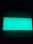
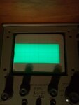
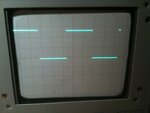
The problem i'm having is - instead of a single horizontal scan line, i get multiple horizontal scan lines. (see attached image).
If i'd have to guess it be something like 10 of them. That's 10 scan lines all bunched together.

Its as if the focus is out - way out. I've check the focus and it "works" - its only suppose to focus one scan line deep and it seems to be doing that. Hard to explain but you can see it working. I've also measure it and the focus is "correctly" applying ~800v-~1200v to the CRT.


I've checked the vertical amp, which control Y defection plates and works. Also if i feed in a single say a 1khz 4vpp square wave, instead of a nice single crisp scan line, i get a this big fat (10 wide) scan lines, but the Y deflection seems to be "working". And of course being a CRO, moving the wave form via the X&Y controls all seem to work too.

The horizontal amp looks like its working - i mean there as 7400 TTL nand gate that does some tricky switching, but roughly measuring the voltage and waveforms seems to be there. The horizontal amp circuit also does the blanking (as well as the alt (dual channel display) and add (adding both channels to the vertical amp)

My question is would the FBT (or circuity) be the cause. The unfortunate part is none of my test equipment is rated above 750ac - so im not able to place any test probes in that area? I was thinking of placing a large 1M 10W resister in the circuit and measuring that - but don't know if that works or if it will load the diode pump circuity too much.. - Any ideas?

Has any one seen something similar? Could the blanking circuity be the cause? Looking at the capacitors (visually) nothing looks strange, no bulges or anything like that. The diodes and the bipolar transistors all conduct.

I'd hate to retire my trusty CRO.

Thanks for any help in advance.

joe
 

There is no image attached so I'm working from your writen description. If it was a flyback/blanking problem I would expect only a single extra trace, the 'real' trace returning to it's starting point. Your description suggests there is something else modulating the X timebase sweep and I'm gong to guess it's a power supply fault which is introducing 50/100Hz or 60/120Hz (depending which country you are in) to the horizontal sweep. First suspicion would be the PSU reservoir capacitors on the low voltage supplies, it doesn't sound like a high voltage problem.

Try changing C264, C265 and C266 first. It is worth spending a little money on fixing it.

Brian.
 
photo.JPG

Thanks Brian,

I think i've attached the 'image' correctly this time. My CRO doesn't have C233 to C299 - however the point not lost.

The power supply provides several feeds (-/-15v, -22V and some others) using my friends CRO im pretty sure they're clean but i'll take another look - i could have missed something.

However, i just noticed (10minutes ago) that when i connected my multi-meter to one of the terminals of the focus POT, the trace returned to a single trace if not briefly (????).

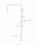
The focus is made of a series circuit starting with -1450V through to 1M5, 2M5 POT (focus) and then a pair of 3M9 resisters to ground. There's also a bypass capacitor (0.01uf) between the pot and ground. I can't check the -1450V directly as none of equipment is rated that high :-( However, i disconnected the bypass cap (0.01uf) hoping to see any changes - none.

Do you still think its low power? Either way i'm checking all the power. (and the bypass caps)

The -1450V is coming from the FBT via a pair of RC circuit and diode. (perhaps i should scan the circuit diagram)

NB: 50Hz (Australia)

PS: happy to spend the money - might have to look for a higher rated multi-meter. Either way hate to see this CRO not operational. Its survived too long to give up now.
 
Last edited:

The diagram would be useful. Looking at the one I have here I can see its for a similar but not identical model so my apologies for the false diagnosis.

It COULD be a simple focussing fault but the fact that you can still adjust it and focus part of the image makes me think that isn't the problem. You should be able to confirm the resistors are OK by measuring them with a Ohmmeter, although rated for high voltage they will still measure as normal resistors. If they are OK at testmeter voltages they should be OK at 1450V.

I would concentrate on the power supply to the sweep oscillator and deflection amplifiers, as there is no apparent pattern to the 'fuzz' I'm guessing it isn't trying to display something but is more likely to be randomly scanning. If you can scan the schematic I might be able to give some pointers to likely culprits. I only have slow internet so if you can make it JPG or better still a PDF it would be appreciated, big files are difficult for me to download.

Brian.
 
A schematic of the CRT related circuit (focus, blanking, HV) would definitely help. I agree that a focus problem seems likely at first sight. The photo doesn't look like "multiple lines" to me, rather a broad band with a halo. Does the brightness control still work?
 
View attachment BWD 525 manual.pdf

Hi,

Thanks for your time. The photo isnt a good one, it does look like a halo, however when you wind up full brightness then it becomes clearer to see the multiple scan lines - only my iphone can't seem to see that detail. So yes brightness still works and works well. :)

Also it seems that a BWD 525 service manual are rare - so i've scanned my in and have attached it.

It contains all the circuit diagrams, descriptions etc. On page 55 has the circuit diagram for the power supply, while on page 36 shows me how to and where to test them.

All the power supplies (except for the -1450V) i can test and have tested. I registered a 45mVpp ripple and the specs are saying <5mVpp for 15V and 10mVpp for the 100V. So soon as i get home i will verify my readings.

If my reading are right then i'll look at the 4700uf filter caps as Brian originally suggested. I'll (happily) kick myself if it ends up being "these" caps - or near by caps.

thanks

Joe
 

Multiple scan lines (I can just believe your report, there's no chance to see it from the photo) would suggest a completely different fault. There must be an unwanted y deflection signal, the trace should reveal (thin scan lines?) if focus is O.K. or not. Faulty power supply filtering (e.g. capacitors dryed out) becomes more likely.
 
Thanks, the schematic helps a lot.

First guess would now be C1 or C2 (or both) are dead. I would think the problem is on the 113V and 100V lines from the power supply. It feeds both deflection amplifiers so any ripple on them will show as deviations in the trace. Note that the reference voltage for the stabilizer comes from the -15V supply through R6 so that could also be suspect. It tells you how much ripple is acceptable but of course you need another oscilloscope to check it!

Brian.
 
pic1.jpgpic2.jpg

Thanks guys - this is awesome..

i do have another CRO at my disposal and i think you might be onto something.

The 135V positive line connecting C1 & C2 has a 9vpp ripple. It eventually gets to the positive side of D5 and i get a 25mVpp ripple coming through.

So C1 & C2 are getting changed and then i'll see what happens. I don't have any caps rated that high so thats shopping tomorrow.

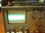
i've also attached a couple photos that i hope shows the problem better for completeness.

NB: the size of C1 and C2 are as big as salt shaker. :)
 

It's worth bearing in mind that capacitors like that have a relatively short life expectancy. They degrade over time even if unused but with constant use will only have a few years before losing efficiency. Over 35 years or so, I would be suprised if they worked well at all. One of the first things done to recondition older equipment is replace ALL the electrolytic capacitors with new ones.

Brian.
 
I'd also note the trace isnt going fully across the display ... unless thats you tweaking
(I've been using my pico for so long I've forgotten how flexible an analogue scope is!)
As Brian says - caps go dry etc.
A brand new can type today will probably have a life expectancy of just 2 years at max operating temperature
and a declining graph as the temp lowers but still - Personally I'd change them all before spending too much
time on other things given the age of the scope. Oh - Yes I see brian said that - course he would sorry!
 
The fact that you saw the trace going back to normal when probing on the focus pot should indicate that there is some problem around the voltage divider assembly (RV52, R78, R77) or the focus pot itself. This is a common problem with scopes when they age. The pots become intermittent or develop cracks in their tracks and go open circuit. One of the resistors in this assembly can also go open circuit or intermittent. Is the voltage on pin 11 CRT (+52V) correct? Make sure all resistance values measure ok.

You should measure about 450V across the focus pot. Be careful with measurements around here as you could damage your meter if not rated for these voltages. You may need to get an HV probe to use with your DVM.
 

Attachments

  • focus_V.gif
    focus_V.gif
    4.8 KB · Views: 90
Last edited:
jdimeglio doesn't have a testmeter rated to that voltage. Although this initially looks like a focus problem, the focus and brightness controls still work and some kind of image within the halo can still be made sharp. That's why I suggested it was interference in the deflection stages rather than a CRT voltage problem.

It's one of those jobs I could probably fix in 5 minutes if it was on my bench and not almost exactly half a planet away !

Brian.
 
However, i just noticed (10minutes ago) that when i connected my multi-meter to one of the terminals of the focus POT, the trace returned to a single trace if not briefly (????).

This would certainly get my attention and focus my troubleshooting around here.
 
thanks guys,

Yea, now that you mention changing the electrolytic caps - seems pretty obvious now. Even if there not entirely the fault it can't hurt. First thing they say in those article about "restoring vintage radios". (derrr)

I've ordered them in - there barrel shaped electrolytic and so want to keep the the authentic look.
eta 5-8 days. :) So i'll expect to go quiet until then..


@E-design, i've checked R77 & R78 and confirmed there resistance. I've check RV53 which is the focus control and confirmed its resistance - first thing i did. Its pin 8 that i placed my multimeter, that resulted in a return to a single trace. RV52 and pin 11 i have yet to check. My multimeter input resistance is measure at 10M, placing the probe must of sank some of the signal. Incidently i replaced the C62 - the 0.01uf bypass cap. - no affect. The voltage i messured across the POT seemed to be inline with what i calculated - so looks like the voltage divide is "working." In a perfect world, i'd just place a CRO on the -1450V or at the POT and see if i can see a ripple - but that would make it too simple :)

Either way i'm recording 25mVpp on the 100V rail and the circuit diagram suggesting that only 10mVpp is acceptable - so current plan is to address that and see if there's any improvements/changes.

PS: forgot how much fun it is messing with discrete components.
 

Its pin 8 that i placed my multimeter, that resulted in a return to a single trace. :thinker:

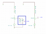
I would take a second look at the focus pot and connection to the resistor network. Measure between all terminals and make sure it is not intermittent over its travel. I suspect a break in the top half of the track to terminal or connection to the resistor assembly. By placing your meter there you basically completed a resistance path between pin 8 and GND, the path that should be completed by the pot and R77/78 and therefore, brought the voltage to within spec on pin 8. (3.9M + 3.9M + 1/2(2.5M)) is close to your meter loading on this point.

One more thing you could try as a test is to take a 10M resistor and solder it between pin 8 node and GND. If that restores the trace, you know you have a problem with the pot or resistive divider.
 

Attachments

  • focus_fault.gif
    focus_fault.gif
    10.3 KB · Views: 95
Last edited:
yup, placing a 2M2 resister on pin 8 to ground reduced my 10 scan lines to about 5 of them.

......and i blew up my TES-2360 multimeter (that one hurts) doh!

im going to replace the entire series of resisters & POT. (and multimeter)
 

SUCCESS - ITS FIXED - See pic.

photo.JPG

synopsis

Ok long story short R77 was open circuited. Replacing R77 fixed it.

E-design your the man although i admit i led everyone astray with my "facts".

So basically i must of stuffed up and couldn't measure resisters if my life depended on it. :)

Before i made this post i measure the series resister and also the POT - at least i thought i did - now i'm not so sure any more.

The only thing i've done differently is use another multimeter, but i think i had a "dumb" moment.

I would like to thank everyone for their input and sincerely apologies for wasting everyone time with my "Johny come lately" posts. Really embarasing.

Now to work out why the scan line doesn't use the entire screen.

:)

Many Thanks


Joe
 

Status
Not open for further replies.

Part and Inventory Search

Welcome to EDABoard.com

Sponsor

Back
Top