Vermes
Advanced Member level 4
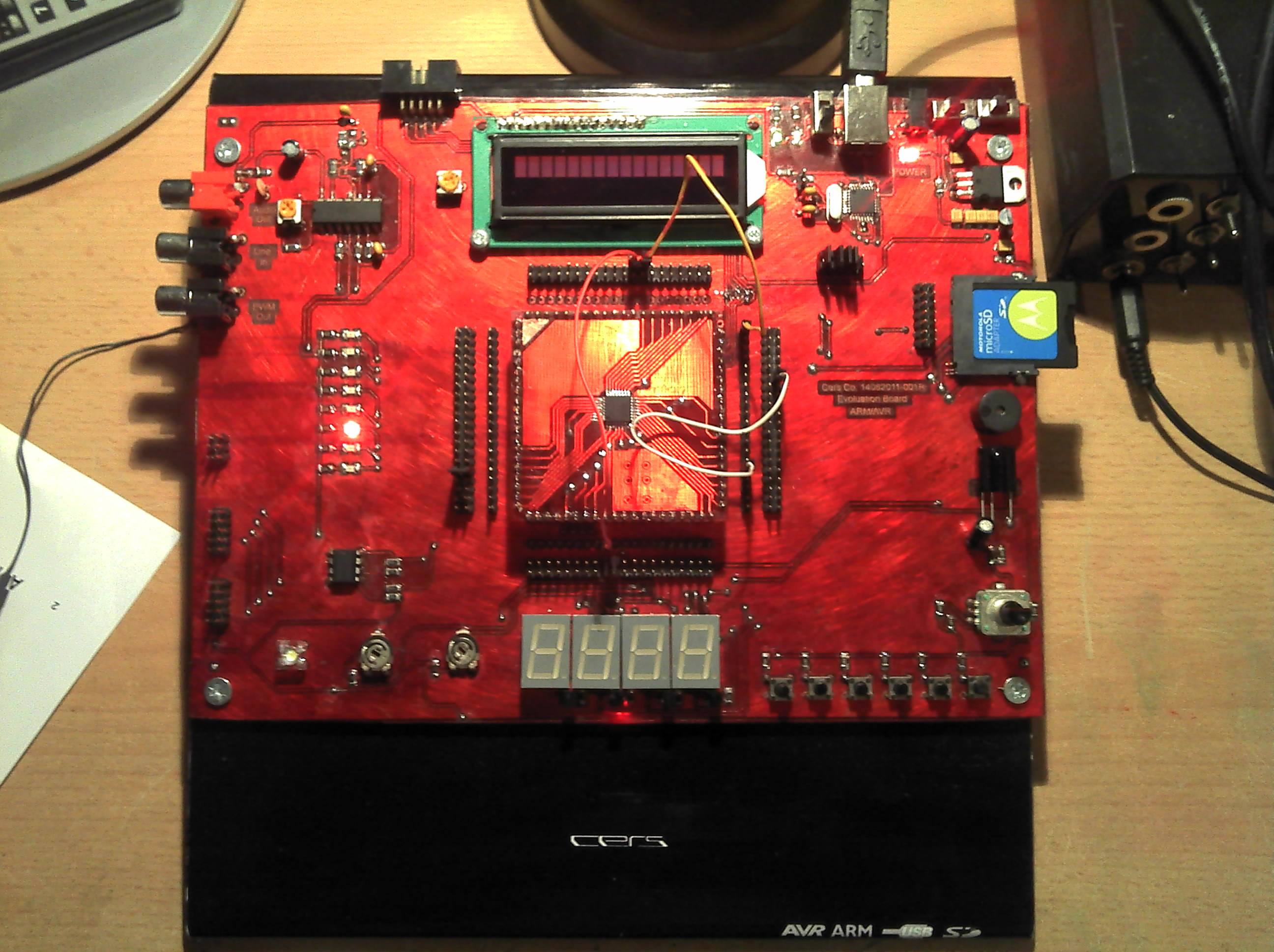
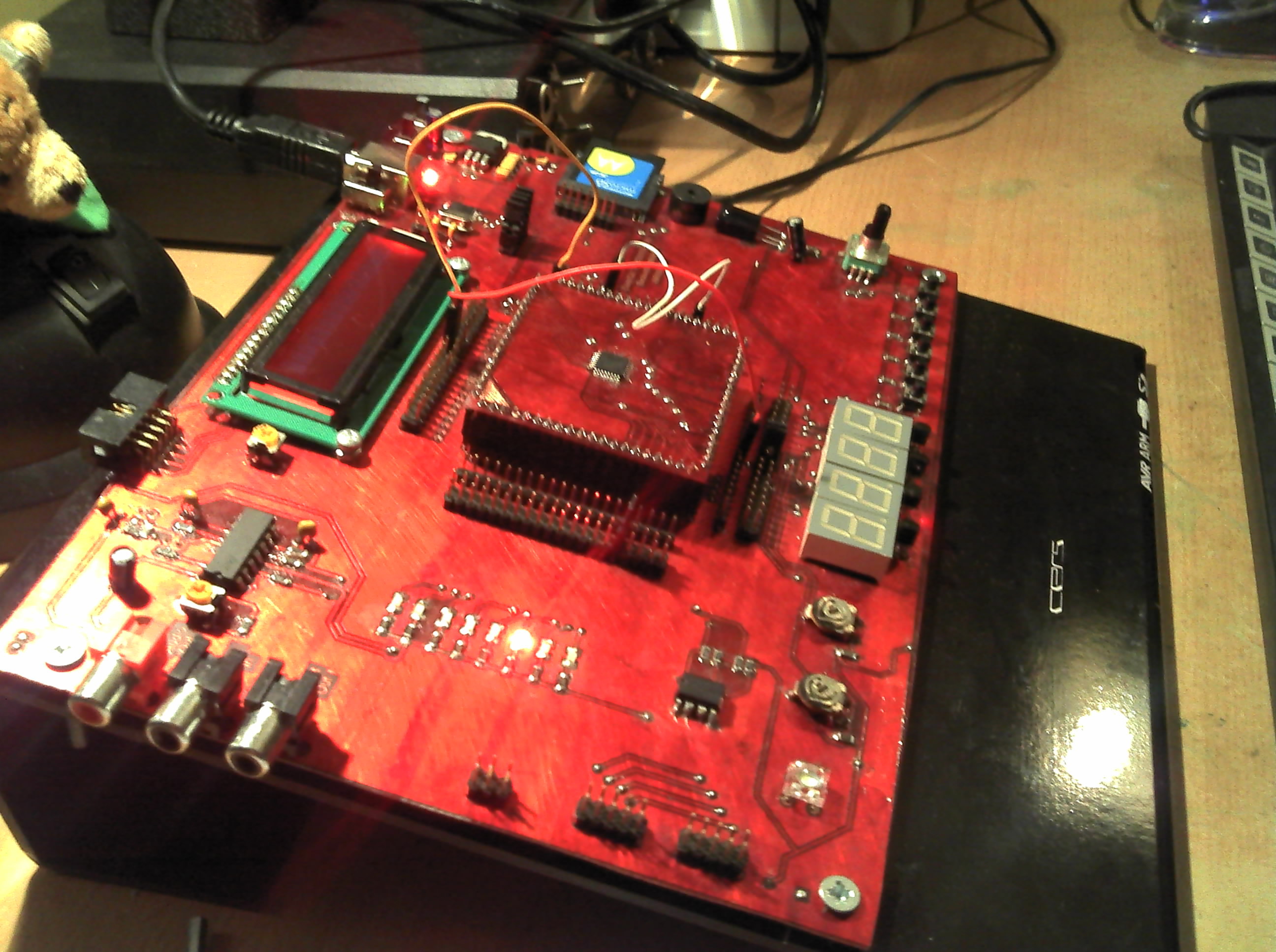
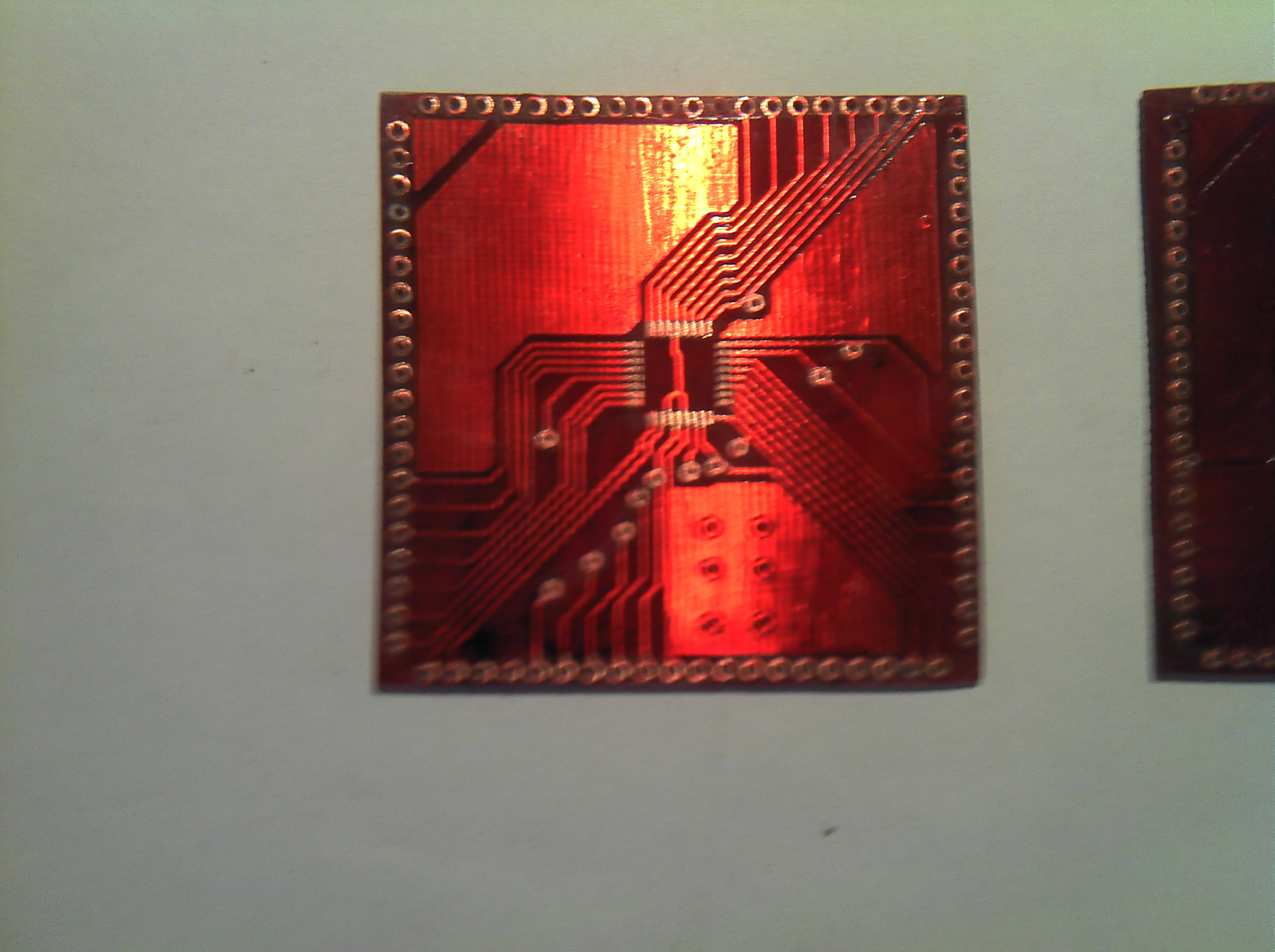
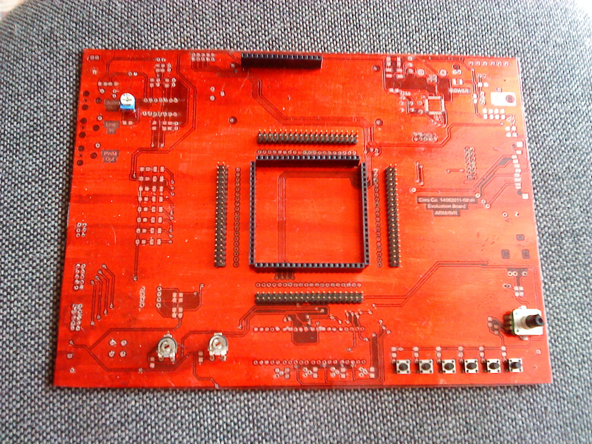
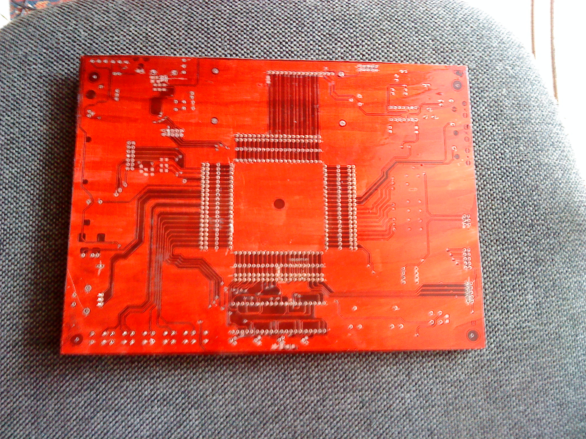
The main assumption was that the device services virtually every microprocessor regardless of whether the housing is a DIP or TQFP. Each processor from ATTINY through M128 to AT91SAM should be supported. What more, all of the peripherals available on the board should be independent from each other and attached to the processor only when it needs them. The same applies to the programmer, whose lines are permanently connected to the terminals used by the current program, even though we are dealing with ISP systems that often cause distortion. Thanks to both the USB supply or/and power supply, external slots with data rails and power, outputs of all peripherals and feet independent derived outside the module, it becomes extremely flexible and easy to use.
The basic device peripherals and features:
- powered from the USB, a 12V power supply, or both at once when there is more demand than 500mA current
- programming by the processor USB embedded in the “nest”, or an external circuit containing the uPc. There is also a possibility to switch the socket to the input mode in order to program the processors other than AVR – e.g. ARM with JTAG
- a possibility to choice of power supply for both the programmed processor in the socket, external uPc
- derived supply pins 3,3V and 5V for boards attached to the device (e.g. LCD)
- derived all the data bus (TWI, USART, etc.) for AVR in two sockets for external systems
- the sockets are doubled what can be used to connect a state/line analyser on USB, so you can see sending and correctness of data between the uPc and I2C system
- SD card slot with a choice of work for processors powered from 3,3V or 5V selectable by jumpers (voltage dividers on the lines of data)
- buzzer
- IR receiver
- rotary encoder with push button
- 6 switch buttons
- 4 seven-segment displays with control transistors (common anode)
- 2 installation potentiometers for manual A/C converters
- Sflux diode for use in PWM control mode
- 24C64 serial memory
- 8 LEDs of any use
- line inputs
- PWM output on RCA socket
- active LPF with adjustable gain amplifier with RCA output (PWM-Line Out)
- input-output socket for programming the external systems, CPU by another programmer (or programming ARM)
- LCD HD44780 in mode selectable 4 or 8 bit with constant or programmatically controlled illumination (PWM)
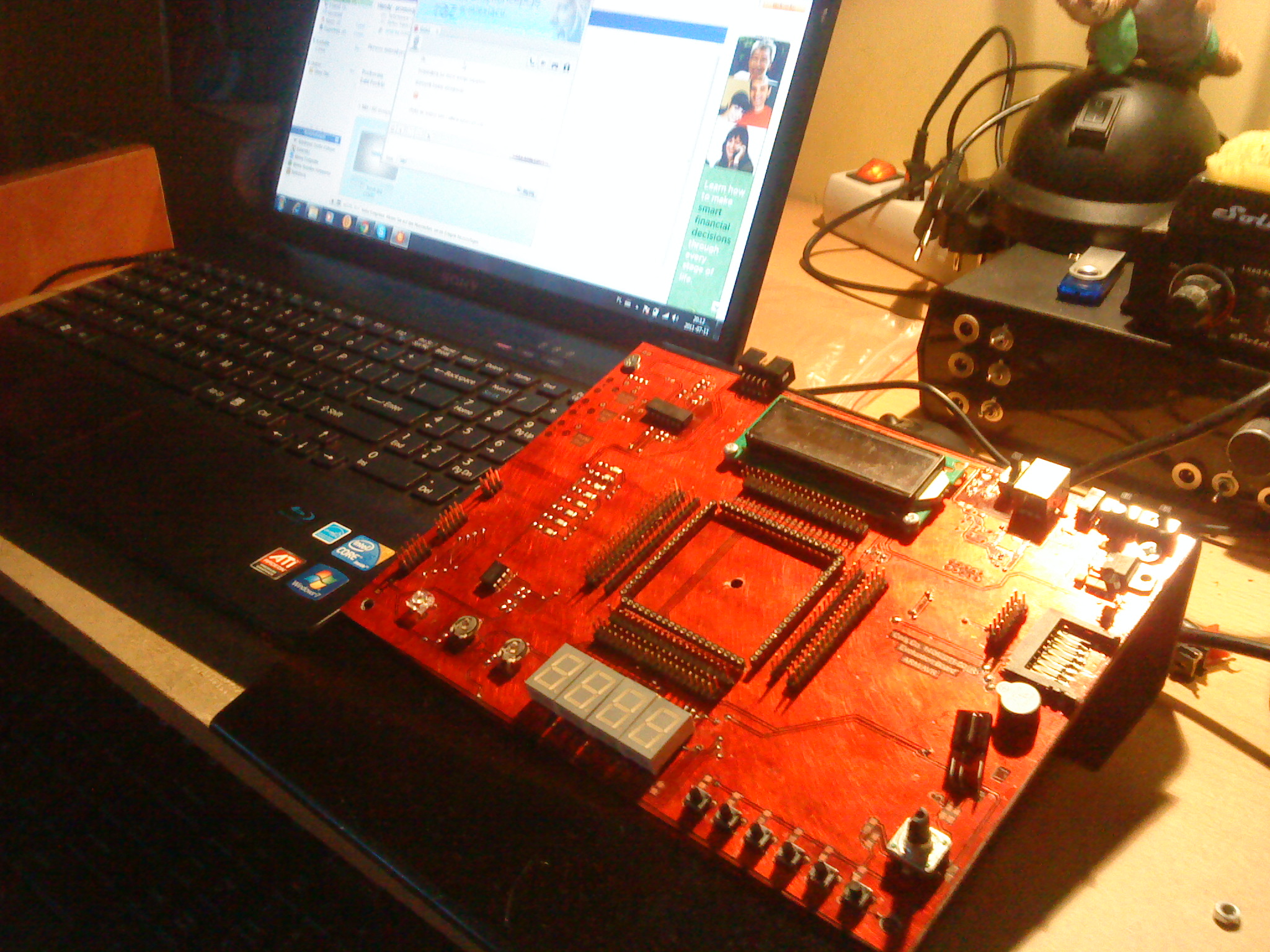
For now there are boards for Atmega8, 16 and 128 (SMD), AT91SAM7S256 and DIP40. In conjunction with the base tilted toward the user, on which there is the system with many of its features and expandability make this set very useful, convenient and easy to use for every electronic-programmer.


Link to original thread (useful attachment) – Rozbudowany układ rozwojowo-badawczy dla procesorów ARM-AVR