Continue to Site
Follow along with the video below to see how to install our site as a web app on your home screen.
Note: This feature may not be available in some browsers.
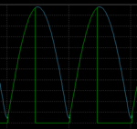
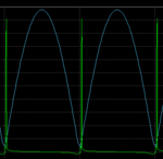
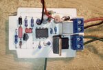
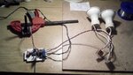
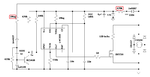
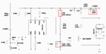
") The impulse is so short and even so they are quite bright. :-o))
The impulse is so short and even so they are quite bright. :-o))