deepsetan
Advanced Member level 4

Hi all,
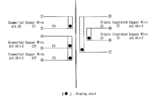
I'm trying to understand transformer winding structure as below:

Based on the transformer structure above, I noticed that there have 3 winding
1. Primary winding : N1, N5, N9
2. Secondary winding : N2
3. Auxiliary winding : N3, N7
However, when I referring to the image of winding internal construction together with bobbin, I start to confuse. Based on Figure 1.0,
1. Primary winding : N1, N2, N3
2. Secondary winding : N4, N5, N6
3. Auxiliary winding : N7, N8
Why the winding structure is difference between Figure 1.0 & Figure 2.0? Based on my understanding, the most internal winding should be primary & follow by secondary winding as other transformer image (example shown by power integration)

I'm trying to understand transformer winding structure as below:
Based on the transformer structure above, I noticed that there have 3 winding
1. Primary winding : N1, N5, N9
2. Secondary winding : N2
3. Auxiliary winding : N3, N7
However, when I referring to the image of winding internal construction together with bobbin, I start to confuse. Based on Figure 1.0,
1. Primary winding : N1, N2, N3
2. Secondary winding : N4, N5, N6
3. Auxiliary winding : N7, N8
Why the winding structure is difference between Figure 1.0 & Figure 2.0? Based on my understanding, the most internal winding should be primary & follow by secondary winding as other transformer image (example shown by power integration)