baileychic
Advanced Member level 3
[PIC] Car Cooling System PSU Design Related
I am doing a Car Cooling system using Peltier (4x) and PIC18F46K22. 2x LM35 are used to sense room temperature and Peltier temperatures. The coding part is almost complete and working fine in Simulation.
For Peltiers connected in Parallel they need a max 15V@15A supply.
I have a need for 12V 3A supply for cooling fans and a 5V 1A supply for MUC+LCD.
There is no time to design a DC-DC Converter and a Battery Charger at this time and hence I am going to use this DC-DC Converter which gives 24V DC from 24V DC input.
https://www.ebay.com/itm/WaterProof...-DOWN-Power-Converter-Regulator-/152975775363
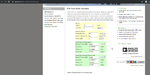
I have attached a circuit which I have designed. It uses a 24V 270W Solar Panel to feed the DC-DC Converter to get 15V DC@20A.
I have used a logic level mosfet and diodes to drop this 15V DC to 14.7V to charge the Series connected 12V 20Ah batteries in Parallel.
I have not yet finalized the used diodes or logic level mosfet. I might change them to better ones with low Vf and low Rds(On) to minimize power loss.
The batteries if 20Ah type needs say 0.1 * 20A = 2A charging current.
My questions are is the circuit in the attached PDF good for a quick solution?
I have no issues with the 12V and 5V DC supplies part in the Power Supply.
For batteries B1 and B2 I have to apply not more than 14.7V boost charging voltage and 11.3V trickle charge voltage. I am planning to use PWM to control the charging voltage and or current.
So, can I use the circuit in PDF?
I have questions related to D1, D4, D5 diodes.
D1 has to block the 24V of battery from getting into Solar Panel.
D4 and D5 should help in charging Battery B2.
The D3 and D4 diodes are for blocking reverse flow of voltage/current from Batteries to DC-DC Converter output.
Will D5 diode gets forward biased while charging the B2 battery and affect the B1 battery charging?
If there are any issues then how they can be resolved?
I am doing a Car Cooling system using Peltier (4x) and PIC18F46K22. 2x LM35 are used to sense room temperature and Peltier temperatures. The coding part is almost complete and working fine in Simulation.
For Peltiers connected in Parallel they need a max 15V@15A supply.
I have a need for 12V 3A supply for cooling fans and a 5V 1A supply for MUC+LCD.
There is no time to design a DC-DC Converter and a Battery Charger at this time and hence I am going to use this DC-DC Converter which gives 24V DC from 24V DC input.
https://www.ebay.com/itm/WaterProof...-DOWN-Power-Converter-Regulator-/152975775363
I have attached a circuit which I have designed. It uses a 24V 270W Solar Panel to feed the DC-DC Converter to get 15V DC@20A.
I have used a logic level mosfet and diodes to drop this 15V DC to 14.7V to charge the Series connected 12V 20Ah batteries in Parallel.
I have not yet finalized the used diodes or logic level mosfet. I might change them to better ones with low Vf and low Rds(On) to minimize power loss.
The batteries if 20Ah type needs say 0.1 * 20A = 2A charging current.
My questions are is the circuit in the attached PDF good for a quick solution?
I have no issues with the 12V and 5V DC supplies part in the Power Supply.
For batteries B1 and B2 I have to apply not more than 14.7V boost charging voltage and 11.3V trickle charge voltage. I am planning to use PWM to control the charging voltage and or current.
So, can I use the circuit in PDF?
I have questions related to D1, D4, D5 diodes.
D1 has to block the 24V of battery from getting into Solar Panel.
D4 and D5 should help in charging Battery B2.
The D3 and D4 diodes are for blocking reverse flow of voltage/current from Batteries to DC-DC Converter output.
Will D5 diode gets forward biased while charging the B2 battery and affect the B1 battery charging?
If there are any issues then how they can be resolved?