+ Post New Thread
Results 1 to 9 of 9
-
16th November 2019, 19:29 #1
- Join Date
- Mar 2017
- Location
- Osaka, Japan
- Posts
- 23
- Helped
- 2 / 2
- Points
- 603
- Level
- 5
Insertion loss reduction for matching networks in PA design
Hi all,
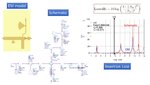
I am now designing an output matching network for a PA operating at 5.8 GHz using microstrip lines on a Roger 4350 substrate. In the schematic and EM models, the insertion loss of this network is relatively high (around 0.5 dB in EM model), this should result in significant reduction of output power and efficiency of PA (please see the figure attached). Could anyone please kindly tell me good strategies to reduce insertion loss in design of output matching network using microstrip line for PA design?
Many thanks in advance!
Attachment 156523
-
16th November 2019, 19:54 #2
- Join Date
- Apr 2011
- Location
- Minneapolis, Minnesota, USA
- Posts
- 13,013
- Helped
- 2587 / 2587
- Points
- 53,227
- Level
- 56
Re: Insertion loss reduction for matching networks in PA design
Hi - Your Attachment 156523 expired unexpectedly. Unless it is duplicated by your second attachment (thumbnail), you may post again with a new uploaded image, and submit the post without delay after uploading.
1 members found this post helpful.
-
Advertisement
-
17th November 2019, 01:32 #3
- Join Date
- Nov 2001
- Location
- Turkey
- Posts
- 4,509
- Helped
- 1359 / 1359
- Points
- 30,746
- Level
- 42
Re: Insertion loss reduction for matching networks in PA design
-You presume that the PA has 50 Ohm Optimum Load Impedance right ?? But it's not practically true..Have you ever really found it as 50 Ohm ?? I don't think so..
1 members found this post helpful.
-
Advertisement
-
17th November 2019, 03:01 #4
- Join Date
- Mar 2017
- Location
- Osaka, Japan
- Posts
- 23
- Helped
- 2 / 2
- Points
- 603
- Level
- 5
Re: Insertion loss reduction for matching networks in PA design
Thank you for your reply and suggestion. The figure is as in the new attachment.
- - - Updated - - -
No, I made the matching network to match the Optimum Load Impedance at f0 to 50 Ohm and terminate 2nd harmonic. Impedance at f0 and 2f0 were found using Load/Source Pull in Keysight ADS based on large-signal model of a GaN HEMT.
Please see the attachments for my design.
Thank you!
-
Advertisement
-
17th November 2019, 10:10 #5
- Join Date
- Nov 2001
- Location
- Turkey
- Posts
- 4,509
- Helped
- 1359 / 1359
- Points
- 30,746
- Level
- 42
Re: Insertion loss reduction for matching networks in PA design
But this Insertion Loss is according to 50/50Ohm Terminations and if you change Optimum Load Impedance with Source Impedance, the Insertion Loss will be quite different.
-
17th November 2019, 10:25 #6
- Join Date
- Mar 2017
- Location
- Osaka, Japan
- Posts
- 23
- Helped
- 2 / 2
- Points
- 603
- Level
- 5
Re: Insertion loss reduction for matching networks in PA design
Thanks for your quick reply.
I am sorry if I didn't get your point. Purpose of my design is making a matching network to transform 50 Ohm to Optimum Load Impedance at f0 and 2f0 with minimum insertion loss at f0 (accounting for both S11 and S21). Hence, I use this equation (50/50 Ohm Termination) as shown in the figure to evaluate this loss. Am I correct or would you mind suggesting alternative methods to evaluate this loss of the matching circuits?
Thank you!
-
17th November 2019, 11:07 #7
- Join Date
- Nov 2001
- Location
- Turkey
- Posts
- 4,509
- Helped
- 1359 / 1359
- Points
- 30,746
- Level
- 42
Re: Insertion loss reduction for matching networks in PA design
No.. You're doing a serious mistake..
If there is a Optimum Load Impedance to be matched to 50 Ohm, the Generator Impedance ( call it as Port-1) will absolutely be Complex Conjugate of this Optimum Load Impedance.
And you have to examine your circuit driven by this Generator with its Internal Complex Impedance.
For instance.. I have designed an Impedance Matching Circuit from 10-j*10 Ohm to 50 Ohm and my Optimum Load Impedance will in this case be 10+j*10 Ohm ( complex conjugate.. see it ?)
And the results Red One driven by 10-j*10 Ohm, Blue One drive by 50 Ohm... Can you see the difference ??
1 members found this post helpful.
-
17th November 2019, 11:56 #8
- Join Date
- Mar 2017
- Location
- Osaka, Japan
- Posts
- 23
- Helped
- 2 / 2
- Points
- 603
- Level
- 5
Re: Insertion loss reduction for matching networks in PA design
Thanks a lot for your clear explanation!
I fully understood your explanation.
However, I wonder how can we evaluate loss of matching circuits taking into account propagation loss of transmission line and return loss. Is just checking complex conjugate at f0 sufficient? How about return loss? Is the equation IL=10*log(1-abs(S11)^2)/abs(S21)^2 correct in evaluation of the loss and in which case this equation is applicable?
Thanks in advance!
-
Advertisement
-
17th November 2019, 13:55 #9
- Join Date
- Nov 2001
- Location
- Turkey
- Posts
- 4,509
- Helped
- 1359 / 1359
- Points
- 30,746
- Level
- 42
Re: Insertion loss reduction for matching networks in PA design
If the Impedance Matching Circuit has been carefully designed, S11,GammaS,GammaL and S22 will all be zero (ideal case) so what rests ?? Just S21.
But they won't be as expected in reality so you have to check GT ( Transducer Power Gain ) who includes ALL possible reflections/mismatches ( source and load ) for the structure.The you have to simulate your circuit in Momentum to obtain realistic result.
1 members found this post helpful.
+ Post New Thread
Please login