Continue to Site

Welcome to EDAboard.com

Welcome to our site! EDAboard.com is an international Electronics Discussion Forum focused on EDA software, circuits, schematics, books, theory, papers, asic, pld, 8051, DSP, Network, RF, Analog Design, PCB, Service Manuals... and a whole lot more! To participate you need to register. Registration is free. Click here to register now.

Scoping the post rectifier DC bus in a 240VAC , 100W PFC'd flyback

Status
Not open for further replies.
T

treez

Guest
Hello
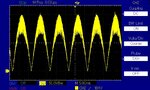
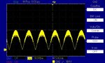
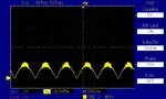
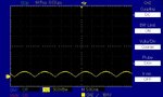
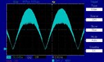
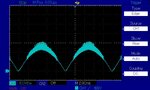
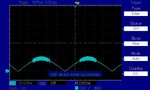
I was scoping the Primary , Post rectifier DC Bus in a 100W, 240VAC, offline PFC’d Flyback to see what the voltage ripple was like on this rail.
As you can see, at the mains peak, there is a lot of noise at the peak of the waveform that makes the measurement impossible.
The blue waveforms were done with a x10 scope probe (with a dangling ground clip) with its lead wound in three turns round a ferrite torroid. The yellow waveforms are done with a diff probe.
I obviously need a ten times coaxial probe without the dangling ground clip.
Do you know of one?...or must I do the old trick of wrapping wire round the ground barrel of the probe?
 

Attachments

  • diff probe _50v per div.jpg
    diff probe _50v per div.jpg
    134.7 KB · Views: 134
  • diff probe _100v per div.jpg
    diff probe _100v per div.jpg
    120.2 KB · Views: 131
  • diff probe _200v per div.jpg
    diff probe _200v per div.jpg
    111.7 KB · Views: 135
  • diff probe _500v per div.jpg
    diff probe _500v per div.jpg
    104.7 KB · Views: 135
  • scope probe _50v per div.jpg
    scope probe _50v per div.jpg
    115.4 KB · Views: 136
  • scope probe _100v per div.jpg
    scope probe _100v per div.jpg
    108 KB · Views: 137
  • scope probe _200v per div.jpg
    scope probe _200v per div.jpg
    108.7 KB · Views: 141

input frequency is 50Hz as seen by the 10 ms for 1/2 cycle

what is the frequency of the PFC stage? i think you're seeing the switching
stretch out the time scale and see if the "noise" looks like a constant frequency
 
  • Like
Reactions: treez

    T

    Points: 2
    Helpful Answer Positive Rating
it appears the PFC is somehow going to a lower sw freq once it passes a certain voltage ( or current ) and this is causing the increase in Vripple observed - can you post the PFC schematic? this could also happen if the choke is saturating or iron powder, kool mu going lower in L as the current climbs up forcing more current ripple for a given sw freq - the fact that it ( the ripple) looks to be progressive in the last screen shot ( yellow ) would seem to suggest iron powder / kool mu toroid going lower in L as I climbs ...

- - - Updated - - -

the increased current ripple - due to variable L choke is causing increase V ripple on the filter caps ...

please send internet procured beer if correct ...
 
  • Like
Reactions: treez and FvM

    FvM

    Points: 2
    Helpful Answer Positive Rating
    T

    Points: 2
    Helpful Answer Positive Rating
Looks tell a lot. This is not regular noise. All the noise is coming from the down side.

the increased current ripple - due to variable L choke is causing increase V ripple on the filter caps ...

And that may be the cause of the untimely passing away of the filter caps (sooner than later)
 
  • Like
Reactions: treez

    T

    Points: 2
    Helpful Answer Positive Rating
Thanks, its Constant off time flyback (off time = 8.2us). I scoped the primary sense resistors and theres no saturation anywhere in the 10ms half cycle.
That ripple shown is on a small capacitor bank comprising
1 x 100n, 1kV, 2220, X7R
1 x 33n, 1812, x7r, 1kV
1 x 10n, 1206, x7r, 1kv
There is a filter inductor just upstream of this small capacitor bank.
 

What is the boost choke --- ?

the PFC flyback is obviously doing more work at higher loads / higher mains, the associated volt ripple on the nearest filter cap will likely see its demise after not too long in the field ... unless it is a very high quality type ...

- - - Updated - - -

what are the temps on the caps you mention when it is going flat out at 230Vac?
 

is there anything different in the variuos scope traces other than the voltage scale and the x10 scope probe and diff probe?

you said its a 100W converter. what is the actual design level and what is the actual power drawn by the load?

i am thinking the converter is overdesigned - the load is too low and it is skipping cycles
is it continuous or discontinuous?
 
  • Like
Reactions: treez

    T

    Points: 2
    Helpful Answer Positive Rating
sorry - brain fade - of course the ferrite Tx is the boost choke - actually flyback Tx performing same function...

your constant off control is part of the issue - the waveforms are normal for the cap sizes listed - you'll have to filter it

p.s. for 100W, (200W peak off the mains for UPF) the peak current in the pri will be 1.4 amps ( average peak ) for DCM at the peak, I/C = dv/dt

thus for the 143nF this gives 80V for the dv for 8.2uS which is about what you are seeing ... voila ...!
 

The first picture is a bit odd, it is almost as if you are going from DCM to CCM for the middle (noisy) part - CCM makes the o/p diodes reverse recover and causes noise - which might be what is being seen in No.1 pic - if so if will be part of the mix in the high Vripple observed in other pics too ...
 

The first picture is a bit odd, it is almost as if you are going from DCM to CCM for the middle (noisy) part - CCM makes the o/p diodes reverse recover and causes noise - which might be what is being seen in No.1 pic - if so if will be part of the mix in the high Vripple observed in other pics too ...
Thanks yes, I believe you are right, the ripple seen is part real and part due to the noise of it edging into CCM at the peak. This flyback was designed for 60W, but we gave it a run at 100W.
On the simulator, there is 0.88ARMS of ripple current in the 143nF ceramic capacitor bank (at 100W operation), therefore, with its low ESR, we believe this to be OK even for 100W. The high ripple voltage on the ceramic capacitror bank seems disconcerting, but since it works fine, we don’t feel inclined to increase the capacitance here for 100W operation.

So it seems the dangling ground clip probe means we get common mode effects in the scope probe lead. Even wrapping it round a torroid three times did not help.

And of course, the diff probe, is terrible here, we cannot even thread the two probes through the torroid, as their shrouds are is too wide.
 

running CCM is a bad idea for RFI noise, as the o/p diode gets quite the hit - this explains the band of noise in pic #1 ...
 

Thanks, its only just creeping into CCM...so the reverse recovery of the output diode wont be as bad as it could be in hard CCM.
But i guess you are pointing out that passing EMC will be much harder?
 
Yup - emc is always measured at worst case - so min AC line max current & max AC line - max load both cases ....
 

Thanks, its only just creeping into CCM...so the reverse recovery of the output diode wont be as bad as it could be in hard CCM.

If you do not mind a little heat, you can perhaps turn on (and off) the drive FET a little softly. Most of the noise (I am afraid) is coming from the hard turn on of the pass transistor. Perhaps if you increase the gate drive resistor a bit...

You have not shown us how the noise looks; same traces but with a faster time base so that we can see the noise more clearly...

Some compromise between efficiency and noise.
 

X7R has a worst case dissipation factor ( tan delta ) of 2.5% for HV caps

The rms voltage during the noisy periods is about 42V rms at sw freq, the current at sw freq is 730mA rms thus the losses are 0.8 watts worst case in the 3 capacitors during CCM operation in the middle part of the mains - the average losses will be lower.

This is perhaps a bit high for these caps for long term operation - but for a commercial / domestic product not operated at full power very often - you may well get away with it - esp for larger pcb lands on the caps to wick the heat away ...
 
  • Like
Reactions: treez

    T

    Points: 2
    Helpful Answer Positive Rating
Yup - emc is always measured at worst case - so min AC line max current & max AC line - max load both cases ....

i thought worst conditions were max line and minimum load, and minimum line and maximum load?
 
  • Like
Reactions: treez

    T

    Points: 2
    Helpful Answer Positive Rating
it is not a constant thing - certainly for a flyback entering CCM - high mains and full load will be an issue - the most stress on the o/p diode ...
 
  • Like
Reactions: treez

    T

    Points: 2
    Helpful Answer Positive Rating
Status
Not open for further replies.

Part and Inventory Search

Welcome to EDABoard.com

Sponsor

Back
Top