Continue to Site

Welcome to EDAboard.com

Welcome to our site! EDAboard.com is an international Electronics Discussion Forum focused on EDA software, circuits, schematics, books, theory, papers, asic, pld, 8051, DSP, Network, RF, Analog Design, PCB, Service Manuals... and a whole lot more! To participate you need to register. Registration is free. Click here to register now.

Signal to noise ratio of the operational amplifier

Status
Not open for further replies.
Hi,

kindly you can see it below, also the Analog Device hand book is considering the noise at the range of signal bandwidth,
the bandwidth set by filters....

As said: I recommend the use of filters to reduce noise.

If you still have any doubts:
Imagine this:
* no input signal
* but the OPAMP and the reisitors will still generate noise.
* unless you suppress this noise ... it will be fed to the ADC ... and the ADC will recognize it...It really is there.

If you need very low noise and low distortion:
Then do additional filtering digitally.
With the use of digital filters you may focus just on the signal of interest (with just a small bandwidth left and right). Maybe with FIR, IIR, biquad or other methods like LIA or DFT..
The noise will be much smaller then.

Klaus
 
I think I have to convert the noise voltage in to peak to peak value, most of the designer use the factor 6.6 to multiply it with the noise r.m.s value

414 uV * 6.6 = 2.7324 mV,

for an ADC with 10 bit resolution and 3.3 V, LSB (voltage) = 3.3 V/2 pow(10) = 3.2 mV.........

is it the way you kindly used ?
 

Hi

weird.

While using peak to peak is a valid option ... and the factor 6.6 is a good rule of thumb....

You need to take care what you do. Don´t compare apples with oranges.
(Before all is seen from the OPAMP)

So - true - now seen from the ADC, the input voltage range may be 3.3V peak to peak, too.
But please verify if the decodable ADC input range really is 3.3Vpp.
(This lets me assume you use VCC as reference. Which I don´t recommend, because you need to include Ref noise (VCC noise) into your overall noise calculations, then. Really bad...)

So if you use the ADC input voltage range, then you also need the analog ADC input voltage of your signal.
Before you calculated with 315mV RMS, which means 0.9VPP.

What now?

If you want to use the full ADC range, then you need an OPAMP circuit gain of 3.3V/0.9V = 3.66.
Thus the noise will be amplified, too...
Then at the ADC surely is higher noise than 414uV RMS.

You can´t use OPAMP_input_referred_noise and ADC_input_voltage_range at the same time.

Klaus
 
You should also have in mind that if your noise is not strictly limited to half the ADC sampling frequency, the ADC upon conversion will fold the noise and although you think you only need to consider noise within your bandwidth, you'll actually get noise from wider frequency bandwidth than this. Noise going to the ADC should be some portion of the ADC LSB, say 1/4 of it for example, so you can leave room for other non-idealities in the ADC.
If you have the noise rms voltage, this is in fact the sigma of the noise random process. So, if you take +/- 3.2 sigma (which is your factor of 6.6), you'll have the pk-pk noise amplitude.

It is generally good practice when you plot noise psd to use log scale for the vertical axis, otherwise you can't see the details, for example the flicker noise corner.
 
Dear friends,

Seems my op-amp has very bad noise performance,

Dear Klaus,

I am using the Vo = 0.9 Vp-p because the output range of my amplifier is limited to this value under unity gain configuration, you might wonder how it is possible, the answer is because I modified the fully differential amplifier to be Differential Difference Amplifier (DDF), and this put me the new limit for the maximum differential input voltage range which is 0.9 Vp-p.

DDF however by other points is just like a fully differential amplifier so I am still keeping referring to it.

My input sensor signal is already large so mostly I will work with unity gain configuration, thus my Vo max = 0.99 Vp-p.

I didn't start yet with connecting to ADC but seems I need to link the ADC input range to the opamp output range, not the opamp output to the ADC input range.

forgive me if I am not explaining the problem well, I appreciate really your help, sometimes problems makes me feel dull..

I just can feel that my opamp with this noise level can not drive ADC, my whole work is gone,,

Dear Klaus,

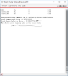
following your explanation about filters, I will assume I have a filter circuit with range 500 KHz to 5 MHz (just because my sensor signal can have a frequency in this range, but mostly 2 MHz), so now I will simulate the noise only in this range assuming the other frequencies are totally killed, here you see the result please

m1.png
m2.png

now I have integrating noise equal to 198 uV
then the approximated peak to peak value = 198 uV*6.6 = 1.3 mV

Do this solve my problem ?

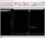
Dear Suta how I can I get the log-log scale of my PSD in cadence ?
 

You either plot the noise in dB scale or you right click on the axis and select Log Scale (which is not a dB scale)
 

Dear Suita, here is the plot with log-log, what is the importance of it over the linear one

y3.png

- - - Updated - - -

Dear Suta,
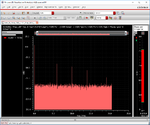
here is aloso the result of the transient simulation with your setting of DFT

Did it agree with our AC noise simulation ?

z1.png

- - - Updated - - -

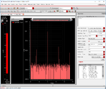
and below is the result of the transient noise but by using the Spectrum tool

z2.png
 

See now in the log-log plot that you can easily identify the important features- flicker noise corner frequency, thermal noise level, any kinks in the PSD, etc. Those were not visible before, when you used linear scale.

I can't tell just by looking at your transient noise simulation results if it agrees with the ac noise. Reason is that I don't know how many points you used for the fft. Basically, you need to integrate the noise and get the total noise, either in power or Vrms and then compare it with the ac results. Integrating basically means that you plot the POWER of the fft and then sum noise from all bins, which is basically the number of the points in the fft. The only thing you have to take into account here is that noise floor is relative to the amplitude of the signal which is at about 0dB in your picture. So, you'll have to scale total noise power respectively.
 
Can you explain why there is no frequency limitation in your noise PSD at high frequencies? Except for that little dip, noise remains more or less flat and if you integrate it you'll get infinite noise power. Maybe that limitation happens at frequencies higher than 1GHz but then what's the point of having such a huge noise BW if you only process single digit MHz signals?
 
Dear Suta,

as I understood from you that my bandwidth for the noise is very wide, actually I just followed your procedure to find the frequency at where the noise saturate after I integrate the noise signal from AC noise simulation, and it was at 250 MHz, so I set this value as the maximum frequency in the transient + Noise setting.

yes my sensor signal is 2 MHz.

Do you suggest me to change the setting ?
 

Do you suggest me to change the setting ?

No, I don't. You showed a plot of the noise PSD that has thermal noise extending to beyond 1GHz. So, I don't really understand how you can get you integral to saturate at 250MHz.
 

Hi,

using a 0.9Vpp input signal on a 3.3Vpp input ADC (you still need to clarify) will degrade resolution.
You will lose about 2 bits .. resulting in about 8 bits overall ADC resolution.

Reducing the decodable ADC input range (usually by reducing ADC_VRef will improve the situation). Read the ADC datasheet.

Klaus
 

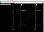
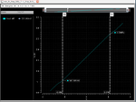
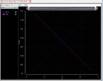
Dear friends, may be better to show you my differential signals at input and output side from the DC simulation, I am showing you kindly the differential output as well as the each output individually ... perhaps I am not describing the quantity well

dif1.png
dif2.png
dif3.png

- - - Updated - - -

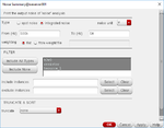
I am sweeping X from -1.65 V to 1.65 V over the VCM voltage of 1.65 V as shown in the setup below

New Doc 43.jpg
 

Status
Not open for further replies.

Part and Inventory Search

Welcome to EDABoard.com

Sponsor

Back
Top