Continue to Site

Welcome to EDAboard.com

Welcome to our site! EDAboard.com is an international Electronics Discussion Forum focused on EDA software, circuits, schematics, books, theory, papers, asic, pld, 8051, DSP, Network, RF, Analog Design, PCB, Service Manuals... and a whole lot more! To participate you need to register. Registration is free. Click here to register now.

PIC18F and PWM problem

Status
Not open for further replies.

trastikata

Member level 1
Joined
Apr 28, 2007
Messages
36
Helped
1
Reputation
2
Reaction score
1
Trophy points
1,288
Activity points
1,631
Hi,

I am trying to implement a PWM on a PIC18F6585. After setting up the PWM registers I get to control the PWM Period and PWM Duty Cycle successfully.

Code:
    'PWM_SETUP
    TRISC.2 = 1         'Configure P1A as input    
    PR2 = 12            'Set PWM period to 2 uS / 500kHz
    CCP1CON = %00001100 'Single PWM output P1A - active high 
    CCPR1L = 6          'Set PWM duty cycle to 50%              
    TMR2IF = 0          'Clear Timer2 Interrupt Flag
    T2CON = 0           'Timer2 prescaller 1:1      
    T2CON.2 = 1         'Start Timer2
    DelayCS 13          'Wait 13 cycles for Timer2 to overflow
    TRISC.2 = 0         'Configure P1A As Output
    ECCP1AS = 0         'Clear ECCPASE bit
    
    'Do something else

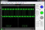
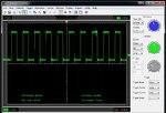
However when I checked with an oscilloscope it looks like that besides the main PWM frequency of 500kHz there is another lower frequency switching on and off the PWM. The following 2 pictures show the same signal - the normal 500kHz output and the 26Hz on-off of the PWM pin. Any idea what is causing it?

Thank you
 

Attachments

  • 500k.jpg
    500k.jpg
    184.4 KB · Views: 58
  • 26.jpg
    26.jpg
    170.5 KB · Views: 65

We need to see the full code to be sure but as a guess I would say you have the watchdog timer enabled and are not resetting it. The result would be the IC shutting down and resetting in a loop.

Brian.
 

We need to see the full code to be sure but as a guess I would say you have the watchdog timer enabled and are not resetting it. The result would be the IC shutting down and resetting in a loop.

Brian.

Thank you Brian.

The first thing I tested was to see if the PIC is resetting by using another pin held high - the PIC is not resetting. Also the watchdog is disabled.

What I find strange is that increasing the PWM frequency over 500kHz (lowering the PR2 value below 12) removes the issue - P1A pin (PORTC.2) is not toggling between on-off.

The full code is the following:

Code:
Device = 18F6585

Config_Start
    OSC = HS	;HS oscillator
    OSCS = OFF	;Oscillator system clock switch option is disabled (main oscillator is source)
    PWRT = On	;PWRT enabled
    BOR = On	;Brown-out Reset enabled
    BORV = 27	;VBOR set to 2.7V
    WDT = OFF	;WDT disabled (control is placed on the SWDTEN bit)
    WDTPS = 32768	;1:32768
    CCP2MX = On	;CCP2 input/output is multiplexed with RC1
    MCLRE = On	;MCLR pin enabled, RG5 input pin disabled
    STVR = On	;Stack full/underflow will cause Reset
    LVP = OFF	;Low-voltage ICSP disabled
    Debug = OFF	;Background debugger disabled. RB6 and RB7 configured as general purpose I/O pins.
    Cp0 = OFF	;Block 0 (000800-003FFFh) not code-protected
    CP1 = OFF	;Block 1 (004000-007FFFh) not code-protected
    CP2 = OFF	;Block 2 (008000-00BFFFh) not code-protected
    CPB = OFF	;Boot block (000000-0007FFh) not code-protected
    CPD = OFF	;Data EEPROM not code-protected
    WRT0 = OFF	;Block 0 (000800-003FFFh) not write-protected
    WRT1 = OFF	;Block 1 (004000-007FFFh) not write-protected
    WRT2 = OFF	;Block 2 (008000-00BFFFh) not write-protected
    WRTC = OFF	;Configuration registers (300000-3000FFh) not write-protected
    WRTB = OFF	;Boot block (000000-0007FFh) not write-protected
    WRTD = OFF	;Data EEPROM not write-protected
    EBTR0 = OFF	;Block 0 (000800-003FFFh) not protected from table reads executed in other blocks
    EBTR1 = OFF	;Block 1 (004000-007FFFh) not protected from table reads executed in other blocks
    EBTR2 = OFF	;Block 2 (008000-00BFFFh) not protected from table reads executed in other blocks
    EBTRB = OFF	;Boot block (000000-0007FFh) not protected from table reads executed in other blocks
Config_End

Xtal = 26               'Use 26MHz crystal

    'PWM_SETUP
    TRISC.2 = 1         'Configure P1A as input    
    PR2 = 12            'Set PWM period to 2 uS 
    CCP1CON = %00001100 'Single PWM output P1A - active high 
    CCPR1L = 6          'Set PWM duty cycle to 50%              
    PIR1.1 = 0          'Clear Timer2 Interrupt Flag
    T2CON = 0           'Timer2 prescaller 1:1      
    T2CON.2 = 1         'Start Timer2
    DelayCS 13          'Wait 13 cycles for Timer2 to overflow
    TRISC.2 = 0         'Configure P1A As Output
    ECCP1AS = 0         'Clear ECCPASE bit
    
    
    While 1 = 1 : Wend  'Do something else - empty loop
 

Hi,

the normal 500kHz output and the 26Hz on-off of the PWM pin. Any idea what is causing it?
My idea:
It's a measurement problem - and no real problem.

It is called "alias frequency" when the sampling rate is less than double of your signal frequency.
--> read about "sampling theorem" and "Nyquist".

Klaus
 

Status
Not open for further replies.

Similar threads

Part and Inventory Search

Welcome to EDABoard.com

Sponsor

Back
Top