Continue to Site

Welcome to EDAboard.com

Welcome to our site! EDAboard.com is an international Electronics Discussion Forum focused on EDA software, circuits, schematics, books, theory, papers, asic, pld, 8051, DSP, Network, RF, Analog Design, PCB, Service Manuals... and a whole lot more! To participate you need to register. Registration is free. Click here to register now.

[SOLVED] Circuit problem finding

Status
Not open for further replies.
Yes, they are not excellent but I think they must work without out problem.

Let's rewind the movie and start over; Indeed, by your statements so far it is clearly noted the lack of some knowledge in the RF field and therefore it is not plausible to assume that it should work even partially mounted, but rather you should only follow the assembly as specified, using components with similar specifications, or with the original values. Another point, show the entire assembly, not only the top face of the board, people just can guess of what are behind that. In addition, check critical parts of the circuit separately whether are working or not, as for example the VU meter and the JFET. And finally, think of using simulators to get you more familiar with those stuffs.
 

Let's rewind the movie and start over; Indeed, by your statements so far it is clearly noted the lack of some knowledge in the RF field and therefore it is not plausible to assume that it should work even partially mounted, but rather you should only follow the assembly as specified, using components with similar specifications, or with the original values. Another point, show the entire assembly, not only the top face of the board, people just can guess of what are behind that. In addition, check critical parts of the circuit separately whether are working or not, as for example the VU meter and the JFET. And finally, think of using simulators to get you more familiar with those stuffs.

VU meter works very well I can show you i can set it on 50 micro amp or grater , and I tested the JFET with multimeter and it's working.
It's working but it didn't react to strong RF fields.
It doesn't work even in the simulator.8-O8-O8-O (also I adjusted POT).

sim.PNG
 
Last edited:

220 Ohms for the gate resistor is way too low. I should be in the MegaOhms range.
The resistor is needed for proper bias of the JFET, but it will also load the wanted signal. In this circuit the resistor should have a very high value.
 

Hi,

(This is an aside: I am unfamiliar with Proteus. Another simulator I am familiar with needs the analysis parameters altered sometimes for oscillator circuits. Simulators are calculators = maths machines, they "just" try to make the numbers add up.)

This is for a cable tracer: "foxhound". It won't help. Worth looking at to notice how the probe section JFET has a resistor and a capacitor in series with the gate, which is more intuitive to me than a diode but I don't understand RF. You don't think you'd need to amplify the input signal, maybe, that the RF signal of interest is uW and the diode may need mW at least or something and that's why you're getting no joy at present? I wonder if a good old 1N4148 would do instead of the (leaky) germanium one, I see them frequently described as substitutes for germanium diodes.

As I said, I don't know about RF, so sorry if the comments are unhelpful.
 

220 Ohms for the gate resistor is way too low. I should be in the MegaOhms range.
The resistor is needed for proper bias of the JFET, but it will also load the wanted signal. In this circuit the resistor should have a very high value.
even 3.3 Meg resistor doesn't work unfortunately.
I think maybe it has a grounding problem but I don't know exactly.

Hi,

(This is an aside: I am unfamiliar with Proteus. Another simulator I am familiar with needs the analysis parameters altered sometimes for oscillator circuits. Simulators are calculators = maths machines, they "just" try to make the numbers add up.)

This is for a cable tracer: "foxhound". It won't help. Worth looking at to notice how the probe section JFET has a resistor and a capacitor in series with the gate, which is more intuitive to me than a diode but I don't understand RF. You don't think you'd need to amplify the input signal, maybe, that the RF signal of interest is uW and the diode may need mW at least or something and that's why you're getting no joy at present? I wonder if a good old 1N4148 would do instead of the (leaky) germanium one, I see them frequently described as substitutes for germanium diodes.

As I said, I don't know about RF, so sorry if the comments are unhelpful.

Thank you so much man your comments and knowledge are great and very helpful.
 

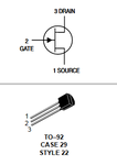
Did you even note that there are no common reference on the above circuit for either the signal generator and the circuit under test? Moreover, the signal generator by itself do not seem like an apropriate model for the antenna, I would expect a current source, but perhaps even the one above should provoke some activity at the transistor side. By the way, did you check the transistor polarity on its library model ? At least at most datasheets, pinout mapping differs from the orientation you placed it on the schematic (D\1-G\2-S\3).
 

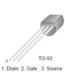
We still haven't seen a picture of the bottom side of your board, but it seems to me that you have mixed up drain and source for the 2N3819 JFET.

2N3819_pinout.png
 

did you even note that there are no common reference on the above circuit for either the signal generator and the circuit under test? Moreover, the signal generator by itself do not seem like an apropriate model for the antenna, i would expect a current source, but perhaps even the one above should provoke some activity at the transistor side. By the way, did you check the transistor polarity on its library model ? At least at most datasheets, pinout mapping differs from the orientation you placed it on the schematic (d\1-g\2-s\3).

we still haven't seen a picture of the bottom side of your board, but it seems to me that you have mixed up drain and source for the 2n3819 jfet.

View attachment 150132


No my transistor polarity is here and it's different.
2N3819.png
 
Last edited:

Lets get a few things sorted out:

It SHOULD work if built properly and using the components in the schematic.
Even without ANY signals being picked up, the meter should read some current and the potentiometer should change that current.

Forget the coil for now, the one pictured is totally unsuitable anyway and you need to get the DC side of things working first.
To achieve that:

1. Replace your meter connections with a resistor of anything between about 220 Ohms and 1K.
2. Put the negative meter probe on the negative side of the battery, leave it there for all the following steps.
3. measure the VOLTAGE at the wiper of the potentiometer with it set one way, at the middle and then then fully the other way.
4. set the potentiometer half way then measure the voltage on all three pins of the JFET.

Tell us the voltages you measure.

Brian.

Voltage on pot 0.2, 3.8, 8.1
JFET:
drain: 7.9
gate:0.1
Source: 4.1
 

Doesn't add up...

If the supply is 9V and the drain voltage is 7.9V there must be current flowing. If there was no current there would be no voltage drop and the drain would measure 9V.
I suspect your meter is not measuring current properly if it doesn't give any reading. If the resistor you used was 220 Ohms, it implies 5mA was flowing, if you used 1K then it implies 1.1mA was flowing.

There is an alternative way to measure signal level, fit a permanent 1K resistor in series with the drain pin and measure voltage (instead of current) from the negative side of the battery to the drain pin. See if that works. If it does, the coil, which is actually a choke should have much higher inductance, try something like 50 turns with of insulated wire with a 5mm diameter.

Brian.

Just my battery is a little bit weak.
I add a new 10 mircro inductor and diode, but still the same results, maybe it needs a really big antenna or grounding to the earth.
Thank you I must test it more.
20181119_010853.jpg

- - - Updated - - -

Did you even note that there are no common reference on the above circuit for either the signal generator and the circuit under test? Moreover, the signal generator by itself do not seem like an apropriate model for the antenna, I would expect a current source, but perhaps even the one above should provoke some activity at the transistor side. By the way, did you check the transistor polarity on its library model ? At least at most datasheets, pinout mapping differs from the orientation you placed it on the schematic (D\1-G\2-S\3).

I used current source instead of signal generator, still zero detection. 10 micro amp and 10 MHZ input current.
new2.PNG

Now it's working on the Simulator after I removed capacitor and diode. but signal is still very weak.
new3.PNG
 
Last edited:

Now it's working, I think diode type is very Important and also Inductor and It needs a good antenna but sometimes gate current can be higher than signal, and adjusting it in the micro amp scale is not easy.
Resistor makes it worse, I don't know why, and the capacitor makes it trash!!!
 

This circuit is a really bad design, Capacitor blocked upper frequencies and inductor blocked lower frequencies, It's sensitivity is very low about a few centimeters.
 

That's part of the reason there is a diode between them.
The inductor is a choke, it isn't supposed to be resonant so it's impedance needs to be high at the frequency you are monitoring.
It will work without the capacitor but it will be LESS sensitive.

You haven't grasped how it works. It is nothing more than an RF voltmeter with an amplifier converting voltage to current. Removing parts is like saying "I took the wheels off my bicycle and it goes faster now".

[edit] Just looked for the diodes you used and they match 1N34A on some web sites. They quote a Vf of 1V at 5mA which is very high for a Germanium diode, most are around 0.3V. It may be worth your while looking for an alternative Ge type -or- using a small signal Schottky diode instead. Suggest BAT85 or 1N6263 for example. [end of edit]

Brian.

I said what I see on the circuit and on the simulator, anyway thank you, the capacitor can make it better a little bit in the very narrow frequency range.
 

The capacitor has nothing whatsoever to do with the frequency range. In theory you could use 1nF, 10nF, 100nF or even higher but there would be no advantage.

Brian.
 

Status
Not open for further replies.

Part and Inventory Search

Welcome to EDABoard.com

Sponsor

Back
Top