Continue to Site

Welcome to EDAboard.com

Welcome to our site! EDAboard.com is an international Electronics Discussion Forum focused on EDA software, circuits, schematics, books, theory, papers, asic, pld, 8051, DSP, Network, RF, Analog Design, PCB, Service Manuals... and a whole lot more! To participate you need to register. Registration is free. Click here to register now.

Reverberation Chamber Simulation in HFSS

Status
Not open for further replies.

nitinwa33

Newbie level 4
Joined
Jun 1, 2018
Messages
6
Helped
0
Reputation
0
Reaction score
0
Trophy points
1
Activity points
68
Hello,

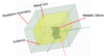
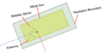
I am currently working on simulating a EM reverberation chamber in HFSS. The structure is a metal box with LPDA antenna and metallic stirrer inside of it. The metallic stirrer rotates around its vertical axis in discrete steps (0 to 360 degrees in 15 degree steps). At each rotation position, a frequency sweep is performed and Electric field data at various points inside the chamber is collected to see if the chamber is statistically uniform.

Dimensions of the chamber: L=6096 mm, W=3962 mm, H=2438 mm, Dimensions of the stirrer (each blade): Ls=1000 mm, Ws=1000 mm


My Approach:

1. I have placed 6 perfect E sheets to form a cube (shown in yellow in the figure) with chamber dimensions and placed antenna and stirrer inside of it.
2. Since a radiation box is needed for an antenna in HFSS, a radiation box (radiation boundary) outside the metal box (shown in figure) is created. I am a bit iffy about this part.

I am running the simulation on a server (with 256 GB RAM) and it takes a little over 24 hours for 6 frequency points between 300 MHz to 400 MHz (at each tuner rotation angle). This is understandable as the volume is pretty large. The problem is I am not seeing uniform electric field inside the chamber.

At this point I am not sure if there is something wrong with the way that I set up the simulation. Also is there a way to reduce the computation time of such large volume EM probelms in HFSS. Please let me know. Any help would be appreciated.

Thanks,
Nitin
 

Attachments

  • RC1.png
    RC1.png
    449.8 KB · Views: 207
  • RC2.png
    RC2.png
    236.9 KB · Views: 99

The problem is I am not seeing uniform electric field inside the chamber.
There will be strong standing waves, more or less different for each frequency and stirrer position. In which sense do you expect an "uniform electric field"?
 

Thanks for the reply. What I meant was, Reverberation chambers need to have ''statisticallly'' uniform electric field with in the working volume (volume enclosed by eight points shown in figure)
RC3.PNG
 

Which properties of your design provide statistical uniform field? I don't see any.
 

Thanks for your reply.

As mentioned before, the stirrer rotates in discrete steps. At each discrete step the boundary of the reverberation chamber is changing (because of the stirrer position). Thus by changing the boundary of Reverberation chamber, statistical uniformity is achieved. Analysis to see if the chamber is statistically uniform or nor can be found in ''CST Simulation of Reverberation Chamber for Improved Field Uniformity''.
 

2. Since a radiation box is needed for an antenna in HFSS, a radiation box (radiation boundary) outside the metal box (shown in figure) is created. I am a bit iffy about this part.

This makes no sense. You only include a radiation box to enable absorption of radiated field. If your DUT is within a metal box, there is no radiation. You can use PEC boundary where the metal box is.

Also is there a way to reduce the computation time of such large volume EM probelms in HFSS. Please let me know. Any help would be appreciated.

For models that are electrically large (in wavelength), consider using time domain instead of FEM. Time domain memory growth is nicer than FEM.
 

Thanks for your reply.

The metal box was formed by 6 PE sheets. Since HFSS cannot ''solve inside'' a PEC material, I thought including a radiation box should solve the issue (as antennas in HFSS need a radiation box to radiate)

From my understanding if we have a radiating element in HFSS, they need to be inside a radiation boundary and HFSS ''solves inside'' this radiation boundary. This simulation setup is equivalent to analyzing a radiating structure (Here LPDA antenna) in open space with perfect E walls as boundary conditions. Please correct me if I am wrong.

Also when you are recommending time domain instead of FEM, are you suggesting me to use a different software or is there a way to perform time domain analysis in HFSS ? Please let me know.

Thanks,
Nitin
 

From my understanding if we have a radiating element in HFSS, they need to be inside a radiation boundary and HFSS ''solves inside'' this radiation boundary. This simulation setup is equivalent to analyzing a radiating structure (Here LPDA antenna) in open space with perfect E walls as boundary conditions. Please correct me if I am wrong.

You are wrong because you don't simulate an antenna problem: there is no radiation to the boundaries and you don't need to sample fields on the boundaries. You just drive a closed resonator box with an antenna inside the box. Radiation boundaries make no sense, use PEC boundaries for the sides walls. The simulation volume is your box then.

Also when you are recommending time domain instead of FEM, are you suggesting me to use a different software or is there a way to perform time domain analysis in HFSS ?

I don't know what features your license includes, but there is a time domain solver for HFSS.
 

I have performed the simulation with only the antenna and the PEC volume box. Unfortunately, I am not seeing any electric field (E-field) inside the box. I Checked the E-field from the antenna, it looks like the antenna is not radiating. I gave it a thought and since HFSS default boundary is PEC and there is no boundary specified, the antenna doesn't radiate. This makes sense.

However, the problem that I am trying to solve is a closed model in HFSS where as the antenna inside this closed model (inside box) can only radiate if its a open model which requires a radiation box. I am totally confused. Any suggestions on how to address such issues ? Any help would be appreciated.

Thanks,
Nitin
 

I am using other 3D solvers (not HFSS) and it works as I described.

Not sure what your problem with HFSS is. You wrote "PEC volume box" and that sound wrong. You don't want a block filled with metal inside. I meant air box with PEC boundaries on the 6 sides (outer boundary of the analysis volume).
 

Status
Not open for further replies.

Part and Inventory Search

Welcome to EDABoard.com

Sponsor

Back
Top