Continue to Site

Welcome to EDAboard.com

Welcome to our site! EDAboard.com is an international Electronics Discussion Forum focused on EDA software, circuits, schematics, books, theory, papers, asic, pld, 8051, DSP, Network, RF, Analog Design, PCB, Service Manuals... and a whole lot more! To participate you need to register. Registration is free. Click here to register now.

Spurs visible on my spectrum analyzer

Status
Not open for further replies.

hafrse

Full Member level 3
Joined
Aug 6, 2007
Messages
169
Helped
1
Reputation
2
Reaction score
3
Trophy points
1,298
Activity points
2,413
Suspected high ripple on SMPS 0.628v at 12v

Hello,

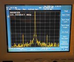
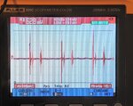
I have a problem with an analyzer which shows spurs from CW 50hz (highest amplitude) , 15hz,350hz,etc... suspected the power supply and checked one of the voltages -12V and there is a ripple of about 0.63 volts, the same ripple is on other output voltages. Is this normal ? problems in the mains rectifier electrolytes (180uf 450V) ?
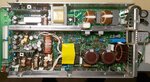
attached a picture of the power supply and trace of the ripple on the -12v.

Thnaks for any input
 

Attachments

  • 20170304_152019.jpg
    20170304_152019.jpg
    594.3 KB · Views: 113
  • 20170304_202819.jpg
    20170304_202819.jpg
    466.9 KB · Views: 118
Last edited:

Re: Suspected high ripple on SMPS

Are you sure this is not any EMI just took by the probe of the scope meter ? Try to make a simple test by short-circuiting both terminals of the probe of this chanel, connecting them to the same energized part of the SMPS (e.g the 12v itself) just to check if the problem persists, which would lead to the conclusion that could be just an issue related to the measurement process. Anyway, considering the narrowness of this artifact, I would not consider this as an issue at the load side in having ceramic capacitors close to the board entry.
 
  • Like
Reactions: hafrse

    hafrse

    Points: 2
    Helpful Answer Positive Rating
Re: Suspected high ripple on SMPS

Are you sure this is not any EMI just took by the probe of the scope meter ? Try to make a simple test by short-circuiting both terminals of the probe of this chanel, connecting them to the same energized part of the SMPS (e.g the 12v itself) just to check if the problem persists, which would lead to the conclusion that could be just an issue related to the measurement process. Anyway, considering the narrowness of this artifact, I would not consider this as an issue at the load side in having ceramic capacitors close to the board entry.

Hello,

You are right, doing as you say shorting the probe and measure at 12v giving lower amplitude an same trace shape, about 0.2v insted of 0.628v , but not sure if that is ok, I am not on expert in SMPS. This instrument has been powered on about 60000 hrs according to its meter, could it be the 2 large filter caps on the primary side that is not filtering enough (high ESR, dried, etc..) the mains 50hz and is modulated to the final 12v output or ground?
Thanks
 

Re: Suspected high ripple on SMPS

I have now moved the smps from the analyzer frame (but still electrically connected) and all the spurs dissapeard!

It seems that the smps is radiating /modulating magnetic/mechanical noise 50hz,150 hz, 350 hz, etc... on the analyzer , picture shows the 50 hz spurs at -134 dbm

How to fix that issue ?
 

Attachments

  • 20170304_145802_rotate90deg.jpg
    20170304_145802_rotate90deg.jpg
    268.7 KB · Views: 90
Last edited by a moderator:

Re: Suspected high ripple on SMPS

if you are measuring ripple, then use a proper ripple probe, eg, a piece of coaxial cable.
Scope leads with dangling tail always show loads of pickup with any smps.
What you show on the scope trace looks like "pickup", that isnt due to the electrolytics being gone, (but i am not saying they are not gone, they might be a bit frazzled, idont know)
 
  • Like
Reactions: hafrse

    hafrse

    Points: 2
    Helpful Answer Positive Rating
Re: Suspected high ripple on SMPS

if you are measuring ripple, then use a proper ripple probe, eg, a piece of coaxial cable.
Scope leads with dangling tail always show loads of pickup with any smps.
What you show on the scope trace looks like "pickup", that isnt due to the electrolytics being gone, (but i am not saying they are not gone, they might be a bit frazzled, idont know)

Hello,
It was a meauring error from my side, there is no electrical ripples
as I stated in my earlier post, I moved out the SMPS from the chassi, and there are no spurs in the display of the analyzer-> no problem at all, if I move back the SMPS into the chassi, spurs will rise again, so I think there is no electrical problem, it should be radiation from the smps to the analyzer boards.

I also isolated the SMPS in its place from the chassi, spurs still there, it is radiated noise.
 
Last edited:

Re: Suspected high ripple on SMPS

oh right, it just shows how much capacitive coupling there is of the smps noise into the chassis.....then the chassis is helping to re-radiate it.
 

Re: Suspected high ripple on SMPS

oh right, it just shows how much capacitive coupling there is of the smps noise into the chassis.....then the chassis is helping to re-radiate it.

I also isolated the SMPS in its place from the chassi by paper, spurs still there, it is radiated noise. So how can I fix that problem? thanks
 

Re: Suspected high ripple on SMPS

Tight pcb layout, good common mode filtering, but gernerally, you cannot realistically fix this...maybe just reduce it a little, but do you care?..if you pass emc then its ok.

- - - Updated - - -

you can also reduce it with screens in the transformer, and flux bands around it, but only do if you fail emc.
 

Re: Suspected high ripple on SMPS

Is there any way to reduce the electromangnetic radiation from the smps by shielding ? can I use steel plates as shielding?
Thanks
 

Re: Suspected high ripple on SMPS

Shielding with metalic materials is a good idea, but it becomes more effective when the case is properly grounded to the Earth, otherwise should consider dissipative materials. Anyway, a good layout is always the best way to prevent issues like that.
 

Re: Suspected high ripple on SMPS

30 MHz interferences (as shown in post #4) will be mostly conducted through cables rather than radiated. In so far shielding of the SMPS has limited effect, filtering the SMPS in- and outputs is the relevant method to reduce it. The dominance of conducted emissions is a simple matter of wavelength versus circuit size.

A SMPS with a switching frequency of some 10 to maximal 100 or 150 kHz won't emit a single 30 MHz line, but a complete "fence" of switching frequency harmonics. Some frequencies might be "amplified" by circuit resonances, but there are surely many interfering frequency. It would be informative to see the full picture instead of only one line with 50 Hz sidebands.
Thanks for your reply, the picture shows a signal on 30 Mhz with spur at 50 Hz, it happenns also in any other frequencies, 10Ghz, 10hz, etc..., even without any signal on the 0 hz spectrum analyzer peak. but doing a larger span, it also shows the spurs with less amplitude also at 150hz, 350hz, etc... (not shown on the picture)
If I move the SMPS about 10 cm away from the chassi and all these spurs dissapears!
 

Hi,

Spurs visible on my spectrum analyzer, please see attached picture. checked power supply lines, all are good. moved power supply from the chassi about 10 cm, all spurs gone. Any idea what could be?
picture shows only the highest 50 hz spurs, but there are more on wider span, at 150hz, 350hz,etc...
Thanks
 

Attachments

  • 20170304_145802.jpg
    20170304_145802.jpg
    289.6 KB · Views: 100

Hi,

Picutre says 30MHz = 30000000Hz
But you say 50Hz

Why there is that huge difference?

Klaus
 

Hi,

Picutre says 30MHz = 30000000Hz
But you say 50Hz

Why there is that huge difference?

Klaus

Hello,

Sorry, I meant 50 Hz spacing from signal carrier. Signal carrier (CW) can be at any frequency, always shows 50hz purs at -134dbm
 

Are you sure that the signal modulation is occurring inside the spectrum analyzer, not in the signal source? It could be e.g. a problem of ground loops.

What's the 30 MHz signal source, how it's connected to the SA? Does the sideband level scale with the input level?
 

Yes, the same problem when tuning to the analyzer 0 hz peak (without any input signal) or any other frequency from an external geberater . The 30 Mhz is the cal signal supplied by the analyzer.
When I move the smps power supply away from the chassi, no spurs are visible any more
 
Last edited:

O.K., suggests that the mains interference is coupled into the oscillator, IF amplifier or detector. There should be no radiated interference at 0 Hz, isn't it.

50 Hz side band suggests that it's not a dried-out filter capacitor (would give 100 Hz ripple) and even 50 Hz harmonics.
 

O.K., suggests that the mains interference is coupled into the oscillator, IF amplifier or detector. There should be no radiated interference at 0 Hz, isn't it.

50 Hz side band suggests that it's not a dried-out filter capacitor (would give 100 Hz ripple) and even 50 Hz harmonics.

Hello,

If I tune the spectrum analyzer at 0 hz , it shows a peak of about -16 dbm, that is normal for most of the spectrum analyzers to show that peak. I have nothing connected to the analyzer, and at 0 hz it also shows spurs at 50 hz spacing from the 0 hz CW peak same as in the picture, then it also shows 150 Hz, 350 hz, etc... peaks with less less amplitudes (harmonics ? ).
Could it be radiation from the mains filter box (integrated with the socket for the power cord )?
 

Status
Not open for further replies.

Part and Inventory Search

Welcome to EDABoard.com

Sponsor

Back
Top