Continue to Site

Welcome to EDAboard.com

Welcome to our site! EDAboard.com is an international Electronics Discussion Forum focused on EDA software, circuits, schematics, books, theory, papers, asic, pld, 8051, DSP, Network, RF, Analog Design, PCB, Service Manuals... and a whole lot more! To participate you need to register. Registration is free. Click here to register now.

Dc Motor power supply

Status
Not open for further replies.

Enzy

Advanced Member level 1
Joined
Mar 20, 2016
Messages
488
Helped
2
Reputation
4
Reaction score
2
Trophy points
18
Activity points
4,607
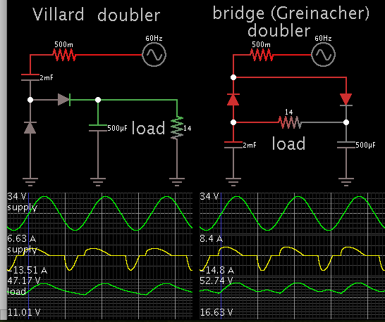
I want to power a Dc motor it ranges are 0-180v 2.3AMPS I have a 10 Amp 12-0-12V transformer I added a rectifier and connected it to the motor and it worked but I am getting between 1.7 and 2 amps current draw with no load, IT runs a conveyor and its a small geared motor I am wondering if its because I am only using 24v to power the motor why the amp range is so high or is there another simple schematic I can use to power it so that the current draw isnt that high.
 

getting between 1.7 and 2 amps current draw with no load

Question: Does it spin slow at such times? Then it sends 2A through each winding in succession. Does the motor overheat? If it happens one time then it degrades performance permanently.

You should never let it stall. If it stalls it can draw extreme current through one winding and burn it up.
 

Yes it spins slow... but the speed is ok because thats how I want it to spin a little faster would be ok as well though. Each winding wouldn't be exactly equal but they were relatively close each time...

I used my hands to hold the conveyor to apply load up to 2.45 amps and had it there for a while over and over for about 10-15 mins and its didnt heat up at all (the motor) If it stall I know it would burn it happened before when someone else set it up but this time I am making a circuit for it I added a 2.5amp fuse even though the motor is rated 2.3 amps its the closest I could find but even running it over the rated current for a period of time it didnt get hot at all.

SO my question is do you think it would use less current if I used Pwm to drive the motor instead of just using a rectifier to send unfiltered Dc to the motor?
 

NO you are driving a DC motor at less than 10% of it's rated voltage so there is little back EMF to reduce the current.

It is like driving a car from a stop light in 5th gear
 

SO my question is do you think it would use less current if I used Pwm to drive the motor

Yes although that also slows down the motor.

Theoretically you might change the gear ratio, so that it requires running the motor at a faster rpm, consuming less current. By definition this would mean running at higher voltage. However this leaves you with a question: Will the amount of Watts change? You need a certain amount of Watts to drive the load. The gear ratio also has something to do with it. These various factors make it hard to predict performance.

When you think about it, motors are complex beasts. You add a load, then apply voltage to spin up the motor at a desired speed. If the motor can handle the load, then you're okay.

You seem to be testing it in a safe manner, by staying close for 10-15 minutes to see if it overheats.
 

Yes I have been testing it for that amount of time because I did some mechanical repairs also by changing bearings and some nuts and bolts... Im not pro at the mechanical stuff..

You seem to be testing it in a safe manner, by staying close for 10-15 minutes to see if it overheats.[/QUOTE]


What if I add a voltage doubler circuit to the 24v dc from the transformer using some 6 amp diodes would that give me a higher voltage at good enough current?

(max ecpected current at 2.3amps.)
 

Did you say the 180V motor has 2.3A rated current and is already consuming 2 A at 24V input with no load?

Either the specification is wrong or the motor is defective.
 

it has a gear attached it to it, thats how it was bought and it is assembled to a small 4ft conveyor belt but while under testing there is nothing on the belt so yes its rated 0-90 0-180v and im just applying 24v and thats the current im getting from each phase
 

thats the current im getting from each phase
Phase? It's a DC motor.

It could be that the mechanical load is causing the high current consumption, e.g. by extensive friction. But it's unlikely that the current decreases with higher speed respectively motor voltage.
 

DC motors are simple if you remember this.. I hope it makes sense.

With no friction or load
1) RPM/Voltage= constant
2) Current = Torque except as RPM increases Back EMF or BEMF opposes the applied voltage and becomes equal at no load or rotational acceleration ( which requires torque )
3) so Torque decreases with speed due to difference between Applied EMF and Back EMF ( which is generated when power is off)
4) Maximum HP is around 80% of full speed as a result.
5) Due to 3) above, Full Voltage Start current is 8 to 10x Rate current at full speed ( unless modified to be low surge type)

- Thus IF you rated current is 2.3A at 180V then the Full voltage start current would be 23A
- Thus with no load at 24V or 24/180=13.3%, I would expect RPM is less than 13% of full RPM and thus current to decreases from 10x to 1x rated current as speed increases.

Thus speed with 13%Vin with no load produces "available torque" of (1-13%)[net EMF]* 13%V = 0.87*13= 11.3% of available torque, so it will be easy to stall but is consuming 13%V*10= 1.3x2.3A =3A (2.3= rated current at full speed and full load)

You are getting 2A instead of 3A so your load is 2/3 of what is available yet only about 10% of max torque available at 13%V and yet the windings ar heating up with conduction losses like it is working at maximum horsepower.

This MEANS your speed/Volt ratio is poorly matched and you don't have enough torque to get the motor to spin at higher RPM while the conveyors runs slower, then kicks into 2nd gear? or your gear friction is too high or something, but your load profile does not match the power available.


Thus ifr motor is rated at
 
So in other words testing it with a higher voltage and checking results would be a good idea. down fault to that is where I am located at the moment transformer is my problem so thats why I was wondering if I couldn't use any form of voltage doubler circuit.
 

I was wondering if I couldn't use any form of voltage doubler circuit.

Simple voltage doublers. Supply is 24VAC.

Capacitors can have low or high values, and can be unequal. By playing with values you obtain various voltage and ripple output.

If your load must have a connection to 0V ground, then use the Villard type.


- - - Updated - - -

If you raise voltage to the motor, then it is important that you watch power and heat levels.

It's also a good idea to minimize friction in the conveyor mechanism. Apply grease, check tightness, check clearances, etc.
 

If transformer is limiting current, then you need to step down /2 voltage with centre tap single diode rectifier on each side in order to get 2x current and 1/4 source impedance. Voltage doubler full bridge rectifier on doublersyour problem with transformer saturation.

then , if possible DPDT switch to separate voltage doubler at half speed, but only if you have a centre tap and two bridge caps , half ad full.

Proper XFMR sizing is a must.
 

Simple voltage doublers. Supply is 24VAC.

Capacitors can have low or high values, and can be unequal. By playing with values you obtain various voltage and ripple output.

If your load must have a connection to 0V ground, then use the Villard type.


- - - Updated - - -

If you raise voltage to the motor, then it is important that you watch power and heat levels.

It's also a good idea to minimize friction in the conveyor mechanism. Apply grease, check tightness, check clearances, etc.

I used Idea to try and make a circuit, I was trying to use a pwm signal and at the same time trying to use a voltage doubler circuit which seems like a typical boost converter circuit I am not sure if all the components are correctly selected but how does this look

- - - Updated - - -


I used Idea to try and make a circuit, I was trying to use a pwm signal and at the same time trying to use a voltage doubler circuit which seems like a typical boost converter circuit I am not sure if all the components are correctly selected but how does this look

- - - Updated - - -


The design is clever but it does not give you such a wide range of output voltage as you wish. I am running simulations, experimenting with various duty cycles, short and long. (Switching frequency unchanged, several kHz). The output barely changes 2 or 3 volts when comparing duty cycles of 20% and 80% duty.

Can your control IC produce the necessary bias voltages to drive your half-bridge?
 

Status
Not open for further replies.

Part and Inventory Search

Welcome to EDABoard.com

Sponsor

Back
Top