Continue to Site

Welcome to EDAboard.com

Welcome to our site! EDAboard.com is an international Electronics Discussion Forum focused on EDA software, circuits, schematics, books, theory, papers, asic, pld, 8051, DSP, Network, RF, Analog Design, PCB, Service Manuals... and a whole lot more! To participate you need to register. Registration is free. Click here to register now.

[SOLVED] Is it possible to overload a MOSFET gate?

Status
Not open for further replies.

JohnJohn20

Advanced Member level 4
Joined
Feb 2, 2012
Messages
111
Helped
0
Reputation
0
Reaction score
0
Trophy points
1,296
Activity points
2,377
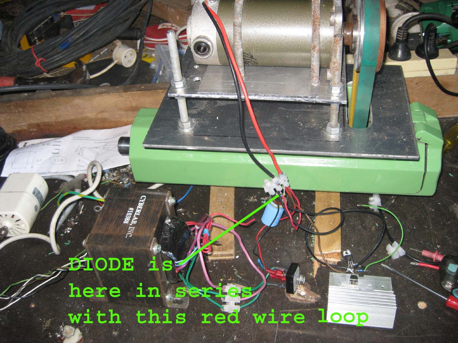
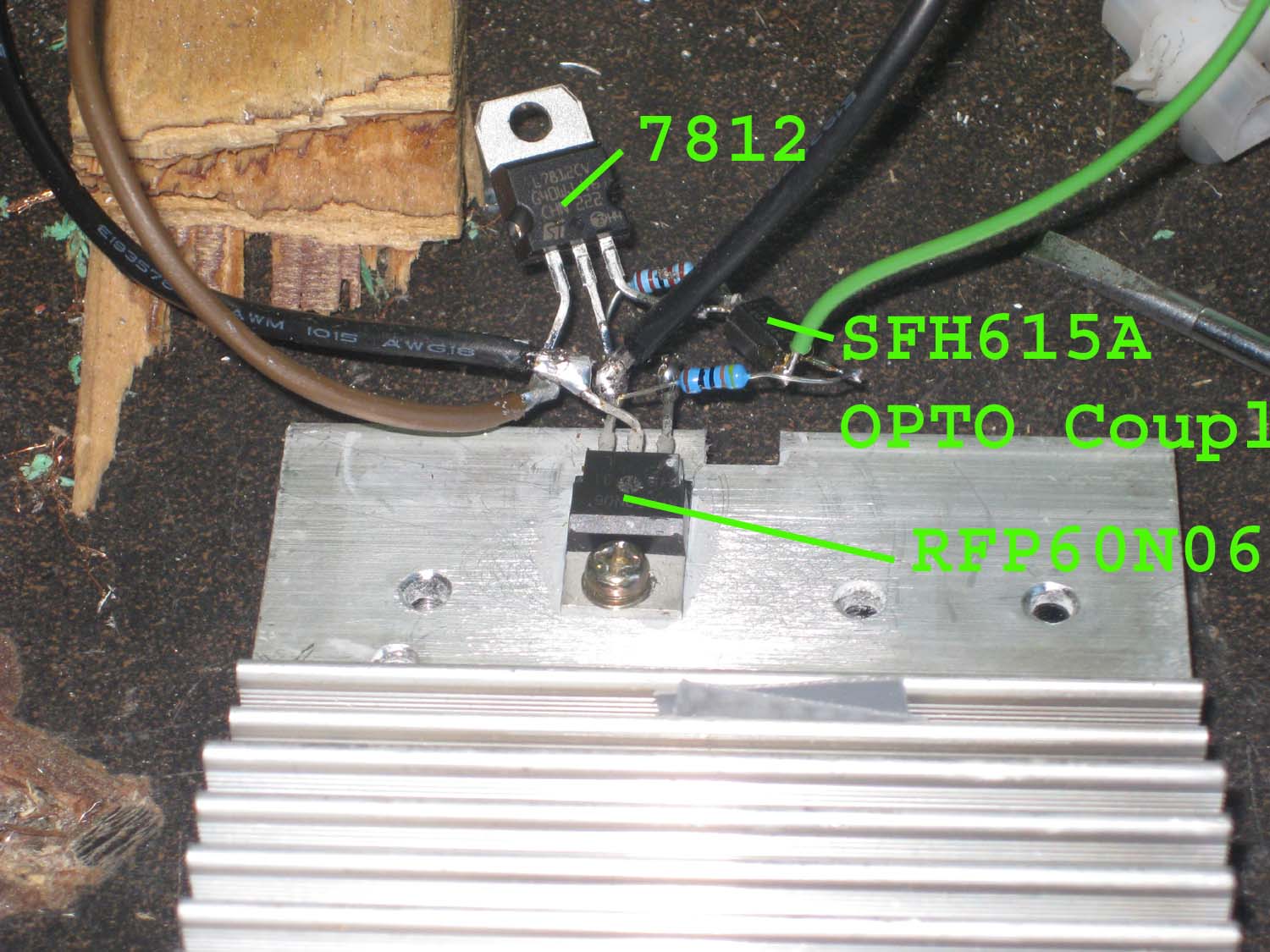
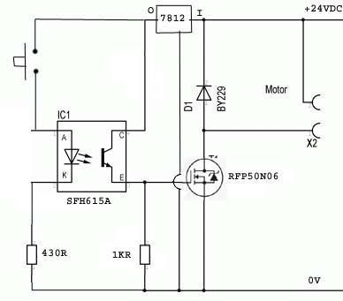
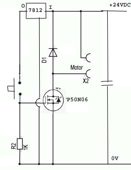
Hi. I am using a RFP50N06 MOSFET to switch 24VDC into a DC motor which can draw up to 15 A. My test circuit was like this:


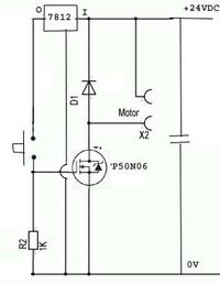
And this worked OK. However, when I increased the DC voltage to 32 V, it workrd for a bit and then the MOSFET shorted inside and wouldn't turn off.

Is it OK to directly connect 12VDC into the MOSFET gate like this? The datasheet says Vgs max of +-20V. Is current an issue here?

I am not sure what diode I have across the motor is. It is a rectifier I salvaged from a small power supply. Could that be an issue?

The MOSFET is mounted on a big heat sink that did not heat up at all.

Any suggestions as to why this happened would be appreciated.

John
 

utc.png

0.023MR*15A*15A=5.175W

maybe The mosfet is too much
 

Its only a 60v device.
My guess is that the back EMF from the motor is creating a short voltage spike that exceeds 60v destroying the mosfet. The gate circuit should be fine.

All of the wiring needs to be very short and direct, as even just a length of wire can have sufficient inductance to generate a mighty kick when you suddenly interrupt 15 amps.

Try connecting a 50v Transorb voltage suppressor with very short connections directly across source and drain.
You probably don't need fifty of them, but this is the type of thing:
**broken link removed**

Also an 18 volt zener directly between gate and source might be good additional insurance.
 
It has a presence D1, no back EMF
 

Hi,

even with D1.. you need careful wiring.
Any stray inductance in the source line or drain line of the MOSFET will cuase a voltage peak.

* You can slow down switching speed (RC on gate, max 10ms)
* or use a zener with very short connections between gate and drain
* or use a zener with very short connections between gate and source (my favourite)

A picture of your circuit (wiring) could help to give better assistance.

Klaus
 
A picture of your circuit (wiring) could help to give better assistance.

Thanks Klaus, well actually it is rather like Christmas tree lights... I will tidy it up and try again.

- - - Updated - - -

View attachment 131845

0.023MR*15A*15A=5.175W

maybe The mosfet is too much

Maybe what? Too much power to dissipate? How would I know? It is secured to a big heat sink with thermal grease.
 

Hi,

I didn´t ask for a schematic, I´m really interested in a photo of your circuit.
I want to see how long the wires are, what copper diameter, where the diode is placed, if the wires are twisted or not, if you have a solid GND concept (like a star connection) and so on...

This all gives us the chance to estimate the voltage peaks on V_DS and V_GS..
Mosfets are sensitive if you overdrive those limits, even for microseconds.

Klaus
 

Thanks Klaus, well actually it is rather like Christmas tree lights... I will tidy it up and try again.
I think that is your problem right there.
If this is some kind of motor test box, wire it up neatly with shortest possible leads around the mosfet.
Short means like one inch long if you can possibly do it.

And fit a transorb and a zener directly right across the mosfet.
Klaus's idea of slowing the switching right down is excellent, and well worth doing.
 
Hi,
I´m really interested in a photo of your circuit.
I want to see how long the wires are, what copper diameter, where the diode is placed, if the wires are twisted or not, if you have a solid GND concept (like a star connection) and so on...

Here you go Klaus. Let me say that originally the circuit diagram was as shown in this new schematic, but when I increased the supply voltage, the opto coupler output promptly died, so I began shorting the opto coupler output with a screw driverwhich was working OK until the MPOSFET shorted inside as described above.

So I guess that once I figure out why the MOSFET died, my next question will be why did the opto coupler die? It is only switching 12V into the MOSFET gate and a 1KR resistor and should be able to withstand 50mA and up to 70 V.


- - - Updated - - -

And fit a transorb and a zener directly right across the mosfet.
Thank you Tony. Right, do you think I could use a 48V 2W zener (actually 2 x 24 V 1W zeners in series) between the MOSFET drain and source instead of the Transorb you described above? The TVS diiode does have huge surge capabilities but are a bit difficult for me to get hold of (unless I buy 50 from the US or 1200 locally from RS)
 

Hi,

Reading datasheets is essential. You might find it booring, I find it booring, too. But there's no way around it.

--> The 7812 needs capacitors. Ceramic type, one at input, one at output, both with very short connection to the 7812' GND.( besides tge existing electrolytic one)

--> screwdriver... optocoupler. Now it's interesting whether the optocoupler output is defective or the input.
Output: maybe the 7812 oscillates without the capacitors. (This may explain, why the FET died, too)
Input: ESD --> then use ESD protection.

As recommended: use overvoltage protection zener on both DS and GS of the Mosfet. Very short connection. 10mm.

The schematic is functionally correct, but includes no protection. It may work in a metal box without external interferance, but as soon as there are wires, that can be touched or are long, you need protection.

You should measure the voltage at input and output of the 7805. Best with a scope and when the Mosfet is switching. Then you can see stability and spikes. Even short spikes (less than 1us) will kill the Mosfet, or other semiconductors.

Klaus
 
A normal zener just does not have the grunt to clamp a 15 amp pulse.
Those transorbs are massively robust, incredibly fast, and will laugh at a short 15 amp pulse.

These transorbs come up all the time on e-bay, so just sit tight. The part number will be 1.5KE xx where xx is the breakdown voltage. They go from about six volts up to over 400 volts. Something between about 30v and 60v should work fine. Often you can buy them individually or maybe sometimes just five.

Very likely when your mosfet shorted out, it also momentarily shorted the drain to the gate, and the opto was just collateral damage when the gate very likely went up over 60v.
 
Hi,
A normal zener just does not have the grunt to clamp a 15 amp pulse.
True. This is what the free wheel diode should do.
But the smaller energy spikes and low power ESD pulses can be handled by a zener. Especially with the recommended slow down of switching speed I don´t expect 15A pulses at the zener.

I agree that transzorbs are more robust. And I agree that the opto may be killed by the defective Mosfet.

Klaus
 
Cheers tony. A quick question about TVS diodes. The 1.5KE51CA diode you mentioned has a Minimum Breakdown Voltage of 48.5V and a Maximum Clamping Voltage of 70.1V. (which is the "maximum voltage drop across the diode at the maximum peak pulse current").

So, does this mean this TVS diode may not be able to protect the MOSFET which has a max drain source voltage of 60V?

Zeners don't have this issue do they? They turn on at the revers breakdown voltage.

- - - Updated - - -

And I agree that the opto may be killed by the defective Mosfet.

The opto died before the MOSFET. That is why I was triggering the MOSFET by shorting the opto output with a screwdriver. More likely I think it was the transient voltage spike coming through the 7812.

So, TVS and zener diodes connected directly to the MOSFET, with capacitors on the 7812 is the plan.

Please tell me if the diode connected across the motor should be mounted near to the MOSFET or near to the motor. Thanks.
 
Last edited:

The 7812 regulator has a max Vin of 35V.
If you get spikes just below this voltage you could drive it into malfunction, especially without any kind of capacitors to stabilize it.
 

Here is the data sheet for Vishay 1.5KE series transorbs.
http://pdf.datasheetcatalog.com/datasheets/120/148853_DS.pdf
The 51A version breaks down between 48.5v and 53.6v measured at 1mA
It will clamp 20 Amps to 73.5v guaranteed maximum.
An average device clamping at 15 amps should in practice do much better than that, especially if its stone cold when hit with a single spike.

You could always specify a 47 volt, or 43 volt device, or even lower. But the 51 volt e-bay transorb I suggested should still protect a 60 volt mosfet (just).

It depends on wiring layout, and where the power diode is located physically how much of a voltage spike actually reaches the mosfet. The ground side is just as important here as the "hot" side.

There are several different things you can do to reduce the problem and protect the mosfet. Fitting a transorb might be the last line of protection after you have tidied up the wiring and slowed the switching speed.

To design reliable equipment, the rule of thumb is first make sure bad things cannot ever happen. Then add a further layer of protection for when when they inevitably do.

One last thought. If after you have carefully shaped and slowed down the switching waveform to eliminate the voltage spike problem.
What happens if a wire unexpectedly falls off the motor during testing ?
 

Hi,

Maybe the optocoupler input shorted with over 23mA current?
 

I'm glad you solved it.

The clamp diode will carry the motor current while it is switched off. So whatever current the MOSFET is rated for is what diode rating you should use. Otherwise the voltage will spike high due to the high ESR of a small diode.
Even worse, the switch may chatter and cause several spikes. A cap across motor can help reduce transient currents,as well as well as twisting your wire pairs to motor and power.
 

I'm not good at English,you can look with an oscilloscope measurements,back EMF
 

The 7812 regulator has a max Vin of 35V.
Good point Gorgon. Thank you. I will probably use a transistor+zener instead. Not sure how this will cope with transients though. I will post that question in a new topic.

- - - Updated - - -

Hi, Maybe the optocoupler input shorted with over 23mA current?
As far as I can tell with my multimeter the opto input still measures like an LED.

The opto output failing is one thing that prompted me to consider that the MOSFET gate was being over driven and drawing too much current through the opto. Cheers.

- - - Updated - - -

You could always specify a 47 volt, or 43 volt device, or even lower.
Not a good idea I think as my 32VAC unregulated power supply floats up to about 42 VDC when there is no load on it.

- - - Updated - - -

What happens if a wire unexpectedly falls off the motor during testing ?
Well bad things do happen! I will first try to cope with the ones I know about.

I think I know how to tidy things up now and will add a 48V 5W zener across the MOSFET and see how it goes.

- - - Updated - - -

I'm glad you solved it.
Thank you!

By clamp diode do you mean the one across the motor or the one across the MOSFET?

- - - Updated - - -

I'm not good at English,you can look with an oscilloscope measurements,back EMF
Ta namen. Good idea. Still dreaming about getting one..
 

Status
Not open for further replies.

Similar threads

Part and Inventory Search

Welcome to EDABoard.com

Sponsor

Back
Top