zhangljz
Member level 5
Hello,
I am using AMS to try mixed signal simulation with two inverters: one is in analog with nmos/pmos, the other is in verilog with "assign out =~in;", and the analog inverter will drive the digital one.
The plot is not very precise as expected that the digital output didn't rise or fall corresponding to the vthi/ vtlo.

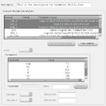
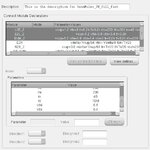
ANd here is my connect rule based on the build-in one "ConnRules_3V_full_fast", and modified the parameters for L2E_2, E2L_2, Bidir_2


Did I miss something?
Thank you.
I am using AMS to try mixed signal simulation with two inverters: one is in analog with nmos/pmos, the other is in verilog with "assign out =~in;", and the analog inverter will drive the digital one.
The plot is not very precise as expected that the digital output didn't rise or fall corresponding to the vthi/ vtlo.

ANd here is my connect rule based on the build-in one "ConnRules_3V_full_fast", and modified the parameters for L2E_2, E2L_2, Bidir_2


Did I miss something?
Thank you.