Continue to Site

Welcome to EDAboard.com

Welcome to our site! EDAboard.com is an international Electronics Discussion Forum focused on EDA software, circuits, schematics, books, theory, papers, asic, pld, 8051, DSP, Network, RF, Analog Design, PCB, Service Manuals... and a whole lot more! To participate you need to register. Registration is free. Click here to register now.

CPW port excitation in CST in simulation conductor backed CPW

Status
Not open for further replies.

kamiar.t

Member level 1
Joined
Sep 19, 2014
Messages
35
Helped
0
Reputation
0
Reaction score
0
Trophy points
6
Activity points
202
hello
how can I do the excitation for conductor backed CPW???
which kind of port???
 

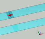
You can use discrete edge ports as is shown in the following image:

CPW_Excitation.PNG

It represents a delta gap excitation. First inside the slot define your delta-gap with dy=Ws and dx=0.7*Ws, where Ws is the width of your slot (gap). You can alter the 0.7 of course. Secondly define your discrete edge port in this delta-gap. Thirdly you can use symmetry planes, a magnetic wall in the yz-plane and depending on your excitation mode a magnetic wall in the xz-plane (differential mode) of electric wall in the xz-plane (common mode). Of course you can also just define an additional edge port if you can not work with symmetry planes.

Sven
 

    sekip

    Points: 2
    Helpful Answer Positive Rating
You can use discrete edge ports as is shown in the following image:

View attachment 114739

It represents a delta gap excitation. First inside the slot define your delta-gap with dy=Ws and dx=0.7*Ws, where Ws is the width of your slot (gap). You can alter the 0.7 of course. Secondly define your discrete edge port in this delta-gap. Thirdly you can use symmetry planes, a magnetic wall in the yz-plane and depending on your excitation mode a magnetic wall in the xz-plane (differential mode) of electric wall in the xz-plane (common mode). Of course you can also just define an additional edge port if you can not work with symmetry planes.

Sven

tanks
you said that i use the descrete port for it?
but point of the feed line i apply the port (x=?) ??
can i use waveguide port for it? and how? please explain it
this G-CPW will feed a horn antenna if it has effect on it
 

hello
how can I do the excitation for conductor backed CPW???
which kind of port???

Hi there,

I would recommend you to put required boundary conditions. As, parallel plate mode and slot mode are easily excited otherwise.

I go for wave guide port size as explained by CST , you can see in CST help section by pressing F1.

However, keeping electric wall in sidewall helps to suppress the parallel plate mode. And, just case to avoid slot (odd) mode, u can place magnetic wall from the center line in feed direction.

Hope this helps!

tanks for your helpful comment
but this G-CPW fed a horn antenna, and a sidewall electric field maybe lead to an error while simulation :(
 

Status
Not open for further replies.

Part and Inventory Search

Welcome to EDABoard.com

Sponsor

Back
Top