Continue to Site

Welcome to EDAboard.com

Welcome to our site! EDAboard.com is an international Electronics Discussion Forum focused on EDA software, circuits, schematics, books, theory, papers, asic, pld, 8051, DSP, Network, RF, Analog Design, PCB, Service Manuals... and a whole lot more! To participate you need to register. Registration is free. Click here to register now.

purpose of two PIN diodes in series

Status
Not open for further replies.

Chao Gu

Junior Member level 1
Joined
Aug 8, 2013
Messages
15
Helped
1
Reputation
2
Reaction score
1
Trophy points
3
Activity points
102
Hi everyone,

Does somebody know the purpose of using two PIN diodes in series as shown in the picture below? To increase the isolation?
Thanks.

QQ截图20141208102800.jpg
 

May be voltage rating? You would better show a complete circuit.
 

2 diodes in series is only for voltage ratings(mostly to drop voltage by ~1Volt).Isolation won't be different for single diode and 2 diode in series.
 

2 diodes in series is only for voltage ratings(mostly to drop voltage by ~1Volt).Isolation won't be different for single diode and 2 diode in series.

It's not true..
The isolation under reverse polarisation condition will be higher than single diode.Because, a PIN diode will act as a small capacitor and when 2 capacitors are connected in series, the total capacitance will be smaller than single one.Thus, the total isolation ( impedance ) between two nodes will be higher.
 

yes two in series will have higher isolation (3 or 6 dB, I forget which), but that is not enough to matter. It would be like the difference in insertion loss of a 0.1 pF series capacitor vs a 0.05 pF series capacitor. i.e. not much difference.

It is usually done for voltage handling in higher power conditions, since each diode has only half the RF voltage across it. But bias structure will be complicated, since you need reverse voltage across both diodes to achieve best isolation. Trying to use a simple bias structure that only treats both diodes as a pair will give you a horrendously long turnoff time.

If you really need more isolation, put a quarterwave line between the two diodes, then you get 2X the isolation of one diode.
 

yes two in series will have higher isolation (3 or 6 dB, I forget which), but that is not enough to matter. It would be like the difference in insertion loss of a 0.1 pF series capacitor vs a 0.05 pF series capacitor. i.e. not much difference.
6dB is a pretty big difference.

Basically this is reasonable if you happen to not be able to find a diode with just the right specifications.
Trying to use a simple bias structure that only treats both diodes as a pair will give you a horrendously long turnoff time.
I don't see why turnoff time would have to suffer, so long as you are pulling the same reverse recovery current out of the pair.
 

RF Power Dissipation at each diode may be another reason of using 2 diodes in series.
 
Last edited:

I don't see why turnoff time would have to suffer, so long as you are pulling the same reverse recovery current out of the pair.

because the two diodes are not perfectly matched, one will turn off quicker than the other. That leaves the other diodes with charge still trapped in the intrinsic region basically with "nowhere to go". Current can not flow thru the turned-off diode, so the diode still on sits there partially turned on still. Eventually those charges recombine, but do so slowly (on the order of tens of microseconds).

So you can turn them on fast, but they are slow to turn off.
You can get around this by separately biasing up each diode with its own bias structure...but it gets more complicated, and there are additional paths for leakage now, etc, so the benefit of the 2nd diode in series is not so much.

it would be much more easy to just shop around for a series diode with half the capacitance, and enjoy the benefit without the drawbacks.

all this is based on the assumption of a silicon PIN type diode. Some GaAs diodes use different carrier types, and switch faster. And FET switches operate much differently, of course
 
  • Like
Reactions: mtwieg

    mtwieg

    Points: 2
    Helpful Answer Positive Rating
because the two diodes are not perfectly matched, one will turn off quicker than the other. That leaves the other diodes with charge still trapped in the intrinsic region basically with "nowhere to go". Current can not flow thru the turned-off diode, so the diode still on sits there partially turned on still. Eventually those charges recombine, but do so slowly (on the order of tens of microseconds).

So you can turn them on fast, but they are slow to turn off.
Okay so you would quickly reach a point where one diode is depleted and fully off, so you quickly get the isolation from one diode. But it takes longer to get the isolation from the second diode. Makes sense I guess.
 

that is EXACTLY what happens. You might need a high dynamic range fast detector to actually notice it is happening, like a log amp detector. you would never see it on a simple schotky diode detector. But you will see the isolation quickly increase to a certain level, then take some time to ramp up to the final isolation value.
 

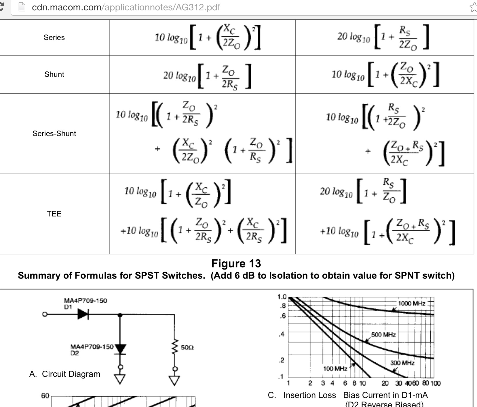
Like any element with real non-ideal component, the characteristics change where all series inductance, resistance and breakdown voltages ADD or x2 and parallel capacitance & leakage current DIVIDES BY 2.

When used as a series - shunt biased switch isolation improves with a larger impedance ratio.
1925327400_1418523261.png
 

Status
Not open for further replies.

Part and Inventory Search

Welcome to EDABoard.com

Sponsor

Back
Top