shan14
Member level 3
Hi
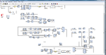
I have an edge detction module implemented in sys gen I have created that model by taking reference of a paper that I fond on net thats why I am not able to understand some part of it
So please help me understand it.
what is the purpose of registers??
also output coming shifted . but when I change the value of virtex2 line buffer to 250 output doesn't come shifted .
where can I get the help for xilinx blockset ??is there any manual?
I have attached the image of model