Continue to Site

Welcome to EDAboard.com

Welcome to our site! EDAboard.com is an international Electronics Discussion Forum focused on EDA software, circuits, schematics, books, theory, papers, asic, pld, 8051, DSP, Network, RF, Analog Design, PCB, Service Manuals... and a whole lot more! To participate you need to register. Registration is free. Click here to register now.

[SOLVED] Help with DC voltage measuring circuit using voltage divider networks.

Status
Not open for further replies.

ankitvirdi4

Member level 4
Joined
Mar 13, 2012
Messages
70
Helped
4
Reputation
8
Reaction score
4
Trophy points
1,288
Location
India
Activity points
1,925
Hello Guys,
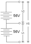
I have a simple application, there are 2 batteries connected in series as shown.
Batteries.GIF
I want to measure the 3 voltages V1, V2 and VS individually. I will be using ADCs to to that, I have upto 6 ADCs.

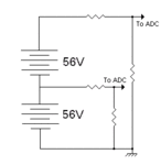
Although making a simple resistor divider network and measuring V1 And VS using ADCs
Prop1.GIF
then calculating V2 in the microcontroller will meet my application needs.

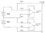
But, I want to measure all 3 voltages, so basically I want 3 DC meters say mtr1 mtr2 and mtrS with range 0-60V, 0-60V and 0-120V respectively. This will give the application a certain flexibility. The user might wanna measure V1 using mtr2 and vice-versa. Or just use them as 3 individual DC meters.

The ideal way to do this is using differential amplifiers I guess similar to this.
prpopamp.GIF

But, Say I don't want to use any opamps at all but just basic resistor divider?

I tried something like this.
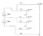
prpres.GIF

The problem here is , mtr1 ADC- and mtr2 ADC- will be negative voltages with respect to ground. ADCs of the microcontroller will not measure that.

So instead of grounding? Say we offset it by some voltage, 1.65V perhaps.
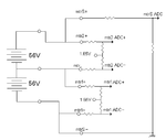
prpres165.GIF

The problem here is 1.65 V to mtr1 and mtr2 ciruits must be isolated from each other, we'll need a buffer for that. That can be made using an opamp or a transistor and it will mostly solve the problem.

Is there any other method? Or another way of isolation? Or can implementing an inverter using an NPN transistor to invert negative voltages to the ADC work?
 

Hi,

often ucontroller ADCs have the possibility for differetial measurement.

So decide the lowest voltage to be your ref GND.
Use a voltage divider for the first battery and feed it to one ADC input.
Use a second voltage divider for both batteries and feed it to the second ADC input.

(Similar to your second picture.)

Now your software should be able to do
* a single ended conversion "Battery1 to GND" (V1)
* a single ended conversion "both batteries to GND (VS)
* and a differential conversion "both batteries to battery1" (V2)

Check ucontroller datasheet on max. source impedance and source capacitance of ADC input for best accuracy.

Klaus
 

Hi Klaus,

* a single ended conversion "Battery1 to GND" (V1)
* a single ended conversion "both batteries to GND (VS)
* and a differential conversion "both batteries to battery1" (V2)
Klaus

Yes, This is excatly what I had in mind when I said

Although making a simple resistor divider network and measuring V1 And VS using ADCs
then calculating V2 in the microcontroller will meet my application needs.

But you see, The application will be very rigid then. There are a few issues like,

1) Say you want to measure some DC voltage A, instead of V2, you will connect only two terminals A+ and A- . The design fails here since there will be no ref GND.

2) If V1 and V2 are swapped while connecting, the design fails.

The third picture is absolutely valid in every senerio , they are like 3 DC meters independent of each other. But, I want to know if there is any other way instead of that. Without opamps? Can there be a simpler circuit?

Thank you for your reply.
 
The third picture is absolutely valid in every senerio , they are like 3 DC meters independent of each other. But, I want to know if there is any other way instead of that. Without opamps? Can there be a simpler circuit?

I certainly do not recommend a purely passive resistor divider network for the following two reasons.

1. To minimize the current drain from the batteries the resistors composing the resistor divider network will need to be of sufficiently high values to minimize current flow.

2. Such sufficiently high resistor values will produce an unacceptable source impedance, for virtual any ADC, which in turn will produce unacceptable levels of error for the measured values.

Most ADCs recommend a maximum source impedance of 2kΩ or less, with a maximum of 5kΩ or 10kΩ with longer than normal sample times and a greater level of error accepted.

There are several reasons to avoid relatively high source impedances when utilizing ADCs, however the two points mention above are probably the most critical when considering your application.

Besides, the required opamps for this specific application would be relatively inexpensive and in my opinion would be certainly of great benefit to the design.

You also might want to consider incorporating one of the many battery monitoring/charging devices designed specific for such an application.

BigDog
 
I think I am gravely mistaken somewhere with my input output impedance concepts, please help me understand it better.

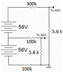
In the following circuit please tell me what will be the source impedance for the ADCs.
res.GIF
According to my understanding it must be 5.6kΩ. If I am wrong please tell me why.

Most ADCs recommend a maximum source impedance of 2kΩ or less, with a maximum of 5kΩ or 10kΩ with longer than normal sample times and a greater level of error accepted.
BigDog
Since I am measuring plain DC Voltage, its fine even if the sampling rate is lower than normal. battery voltage levels won't change suddenly I suppose. But I get what you are saying here.

Besides, the required opamps for this specific application would be relatively inexpensive and in my opinion would be certainly of great benefit to the design.
BigDog

Yes, I agree using opamps is definitely a better way. I just want to know If there can be any other design, which may have its limitations in terms of accuracy or any other factor but is more cost effective?
 

Hi,

In the following circuit please tell me what will be the source impedance for the ADCs.

consider both resistors of the voltage divider to be paralleled.

In both cases the source resistance is about 5.6k.
* 100k || 5.6k and
* 300k || 5.6k


measuring rate:
I recommend to use at least 100nF in parallel to both 5.6k resistors.
this gives a time constant of 560us or a f_cutoff of 284 Hz. A 1uF is even better.
Use good quality ceramics (X7R with 10 times voltage rating) or - if you need it even better - foil capacitors.

I also agree that the OPAMP solution is better. But even without OPAMPs i expect errors < 1% at low sampling rate.

Klaus
 
Hi klaus,

I also agree that the OPAMP solution is better. But even without OPAMPs i expect errors < 1% at low sampling rate.

How to achieve the 3rd condition (with 2 differential circuits and one resistor divider) without opamps?
 

Hi,

if you need to convert 3rd solution as differential measurement, you have to choose _equal_ voltage dividers for both channels.

***
i personally tend to measure two single ended channels and subtract in software - instead of differential ADC measurement.


Klaus
 
  • Like
Reactions: ankitvirdi4

    V

    Points: 2
    Helpful Answer Positive Rating

    ankitvirdi4

    Points: 2
    Helpful Answer Positive Rating
Status
Not open for further replies.

Similar threads

Part and Inventory Search

Welcome to EDABoard.com

Sponsor

Back
Top