Continue to Site
Follow along with the video below to see how to install our site as a web app on your home screen.
Note: This feature may not be available in some browsers.
Are you sure about instability? Which functions do your diagrams show?Hi.
My op amp is unstable. However, I don't want to reduce gain and bandwidth. Is there a frequency compensation method that only change phase without affect to gain?
]
Are you sure about instability? Which functions do your diagrams show?
I meant closed loop bandwidth.More than that, as you don´t want to "reduce gain and bandwidth": Do you speak about open or closed-loop gain?
Could you suggest some methods?There are method to realize stable closed-loop gains - even in case the opamp is not universal-compensated.
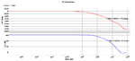
1) Stability check is based on LOOP GAIN response. However, your closed-loop response looks good (in particular, the phase function shows no abnormal behaviour)Yes, I plotted Vout/Vin of op amp in closed loop.
Could you suggest some methods?
Could you tell me why it is normal?1) Stability check is based on LOOP GAIN response. However, your closed-loop response looks good (in particular, the phase function shows no abnormal behaviour)
Could you explain why?The phase is apparently wrongly annotated, it should start at -180°.
Could you tell me why it is normal?
From the picture, it is clear that while phase shift frpm 0 to 180 degree, gain is still big.
At 180 degree, Av = 39.41dB.
Could you explain why?
I don't think it is wrong. I simulated it in cadence.
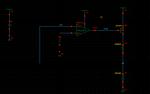
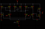
The op amp internal schematic shows no compensation, so naturally it will be unstable. An op amp without compensation is basically a comparator. /QUOTE]
Perhaps it is helpful to complete the sentence:.....it will be unstable for feedback factors above a certain limit (equivalent to closed-loop gains below a certain limit).
An opamp as a stand-alone unit never can be "unstable".
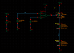
You'll "measure" the gain in small signal analysis. It uses an AC, not a sine voltage source. To get correct results, you have to assure a correct bias point. That's not necessarily achieved by applying 0 V input differential voltage to an OP, at least you need to check the DC output level. Better use DC feedback to set the bias point.The loop gain = Tout/Tin
Tin is a sinusoidal voltage.
Not sure why my picture for gain and phase of loop gain is damaged.
The result is that at for loop gain, phase starts at 180 degree.
As gain falls to 0dB the phase is -22.4 degree. That is unstable.
Of course, that's true. I was referring to the ops use of the opamp in his posted circuit showing a feedback loop.The op amp internal schematic shows no compensation, so naturally it will be unstable. An op amp without compensation is basically a comparator. /QUOTE]
Perhaps it is helpful to complete the sentence:.....it will be unstable for feedback factors above a certain limit (equivalent to closed-loop gains below a certain limit).
An opamp as a stand-alone unit never can be "unstable".