Continue to Site

Welcome to EDAboard.com

Welcome to our site! EDAboard.com is an international Electronics Discussion Forum focused on EDA software, circuits, schematics, books, theory, papers, asic, pld, 8051, DSP, Network, RF, Analog Design, PCB, Service Manuals... and a whole lot more! To participate you need to register. Registration is free. Click here to register now.

Push Pull Class E load location versus LC filter location

Status
Not open for further replies.

gbugh

Member level 5
Joined
Mar 15, 2013
Messages
80
Helped
1
Reputation
2
Reaction score
1
Trophy points
1,288
Location
Fort Worth, Texas
Activity points
2,236
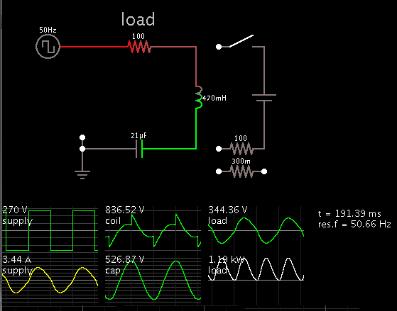
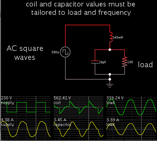
Most push pull class E topologies I've seen have the output L and C and load R all in series. But here Wong shows the load R across the filter capacitor of the output LC filter:

http://www.eie.polyu.edu.hk/~cktse/pdf-paper/ISCAS05-Wong.pdf

Which way is better and why, with the R (output coupling transformer) in series or with the R across the filter capacitor?

thanks, George
 

Attachments

  • US5151852_Push_Pull_Class_E_DC-DC_Conversion.gif
    US5151852_Push_Pull_Class_E_DC-DC_Conversion.gif
    19.9 KB · Views: 101
  • US5327337_1994_Push_Pull_Class_E.gif
    US5327337_1994_Push_Pull_Class_E.gif
    10.9 KB · Views: 103
  • Wong_2005_Push_Pull_Class_E.gif
    Wong_2005_Push_Pull_Class_E.gif
    13.7 KB · Views: 108

I think the resistor R should be in series with L and C, and not in parallel with C.
Anyway, in a Class-E amplifier matching network, if R is in parallel with C you lose more output power than placing the same R in series with L and C.
 

If you put R and L and C in series...

* Square waves (from the H-bridge) need to be greater amplitude.

* L needs to be greater Henry value. C needs to be lower value.

* It requires more careful tweaking of L and C to obtain sine waves. That is, to reach the ideal condition where resonant action coincides with switching transitions.

* Less waste of power (as compared to putting load in parallel with C).
 

So if I want to have the best efficiency I need all 3; R, L and C in series?

If I use a step up transformer to couple to the load then I don't really need a greater amplitude for the topology of RLC in series, right?

If I have a coax cable air core or very low loss core VHF transformer I shouldn't have much efficiency loss from the step up transformer, right?

If you put R and L and C in series...

* Square waves (from the H-bridge) need to be greater amplitude.

* L needs to be greater Henry value. C needs to be lower value.

* It requires more careful tweaking of L and C to obtain sine waves. That is, to reach the ideal condition where resonant action coincides with switching transitions.

* Less waste of power (as compared to putting load in parallel with C).
 

So if I want to have the best efficiency I need all 3; R, L and C in series?

Tentatively, yes. I also forgot to say series RLC can get by on less amperes, even though the incoming square waves need to be greater voltage amplitude.

My observations come from playing with simulations. Your real-life circuit may show different results.

Series LCR, 100 ohm load. Resonant frequency 50 Hz, shown at bottom right. (This readout only appears if I include the extraneous components.)


LC filter low-pass filter, similar to butterworth type (or 2nd-order bass crossover).


In the second case I think the sinewave distorts more with small changes in L or C or R.

There are numerous variations and configurations, which ought to be examined too.

Also there is the PWM sine wave method, with its own filtering requirements.

If I use a step up transformer to couple to the load then I don't really need a greater amplitude for the topology of RLC in series, right?

A transformer complicates things. It will require another run of simulations to get any idea about what voltage you want to come from the secondary, etc.

My simple experiments consisted of adjusting the square wave amplitude until I obtained 340 V sine peaks at the load. When I changed component values in the butterworth style LC filter, it caused large jumps in output voltage.

If I have a coax cable air core or very low loss core VHF transformer I shouldn't have much efficiency loss from the step up transformer, right?

I guess I am not familiar enough with this type of transformer to answer.
Perhaps it applies to a class E of a different nature than I have been talking about?
 

I guess I am not familiar enough with this type of transformer to answer.
Perhaps it applies to a class E of a different nature than I have been talking about?

I'm talking about a transformer kind of like this: **broken link removed**

with or without a core, as a core may or may not be needed depending on how high of frequency I can run the mosfets at.

The transformer would be used like in Figure 3 topology here: www.google.com/patents/US5151852

According to this xls calculator link below, for each half of the Push-Pull Class E, it looks like my source resistance will only be around 1 ohm so I'm thinking I can step the output up a by at least 1:4 if not more.

www.amwindow.org/tech/excel/ClassE_PA_design4c.xls

- - - Updated - - -

I was interested in the coax transformer because the greater primary surface area which would have lower losses from the skin effects at VHF frequencies.
 

Yes, your knowledge will have to guide you in this area. At my level of knowledge, I saw the picture of the coil and thought 'That looks just like a paper clip, and how can they charge $26.50 for it?'
 

Status
Not open for further replies.

Part and Inventory Search

Welcome to EDABoard.com

Sponsor

Back
Top