erchiu
Member level 5
- Joined
- Apr 7, 2012
- Messages
- 93
- Helped
- 2
- Reputation
- 4
- Reaction score
- 1
- Trophy points
- 1,288
- Location
- Rome - Italy
- Activity points
- 2,082
hello everyone,
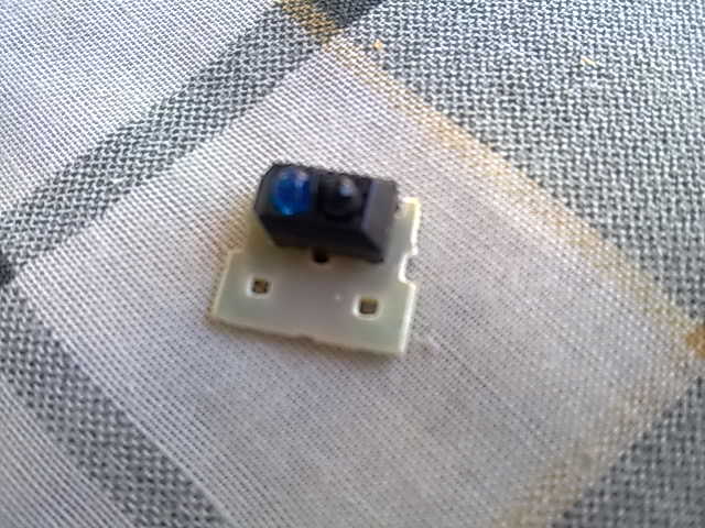
i have an tcrt5000 and i would use it for controller the crossing of objects at an reach of 20/30 cm.
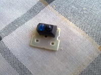
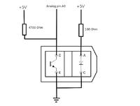
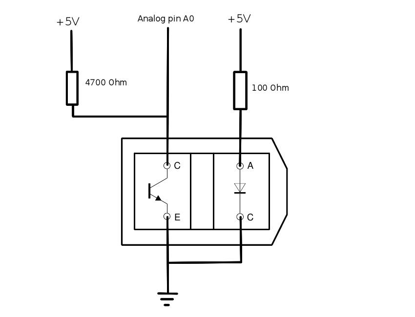
in the web i find an diagram for the connect this component, but i think that the consumption is very high in standby state.
i tried also others connecting with pnp transistor, but the final outcome is that it is a lot sensitive to environment light.
you can help me solve this problem?
thanks at everyone
i have an tcrt5000 and i would use it for controller the crossing of objects at an reach of 20/30 cm.
in the web i find an diagram for the connect this component, but i think that the consumption is very high in standby state.
i tried also others connecting with pnp transistor, but the final outcome is that it is a lot sensitive to environment light.
you can help me solve this problem?
thanks at everyone