Continue to Site

Welcome to EDAboard.com

Welcome to our site! EDAboard.com is an international Electronics Discussion Forum focused on EDA software, circuits, schematics, books, theory, papers, asic, pld, 8051, DSP, Network, RF, Analog Design, PCB, Service Manuals... and a whole lot more! To participate you need to register. Registration is free. Click here to register now.

tcrt5000 sensor proximity

Status
Not open for further replies.

erchiu

Member level 5
Member level 5
Joined
Apr 7, 2012
Messages
93
Helped
2
Reputation
4
Reaction score
1
Trophy points
1,288
Location
Rome - Italy
Visit site
Activity points
2,082
hello everyone,
i have an tcrt5000 and i would use it for controller the crossing of objects at an reach of 20/30 cm.
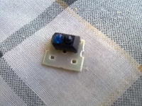
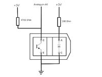


in the web i find an diagram for the connect this component, but i think that the consumption is very high in standby state.
i tried also others connecting with pnp transistor, but the final outcome is that it is a lot sensitive to environment light.
you can help me solve this problem?
thanks at everyone
 

hello everyone,
i have an tcrt5000 and i would use it for controller the crossing of objects at an reach of 20/30 cm.


in the web i find an diagram for the connect this component, but i think that the consumption is very high in standby state.
i tried also others connecting with pnp transistor, but the final outcome is that it is a lot sensitive to environment light.
you can help me solve this problem?
thanks at everyone


This is a reflection IR sensor. This explains the high current needed to achieve the long range.
Also the ambient light effect is apparent.
One solution to both problems is to modulate the LED by say 1 kHz pulses, and to use a selective amplifier after the detector. To add some more protection from the ambient light, find an IR filter that only passes the IR light.
Detection of objects can also be improved if they reflect more. You can use aluminum strips or IR reflective fabric to extend the range.

Pulsed excitation can decrease the current by ~50% with symmetrical pulses, and more with a smaller duty cycle. A 555 timer can do it all. You can use NE 567 as the ~1 kHz detector to reliably detect reflecting objects.

thank you for the answer.
i don't know a lot about ne567, but i understand that must sent to the TX diode not one linear signal but an impulse signal.
in this time i am using for my little experiments of electronic, an interface with an microcontroller (PIC) and it have an output PWM.
i can use it for to drive the TX diode with an impulse signal?
thanks you at all
erchiu

Yes, you can use a TTL signal to feed the LED. Make sure you put a 220-Ohm resistor in series with the LED.
Modulated light and selective amplifier after the photodiode help to separate the useful light from the ambient light, and improves the detection rAnge by reducing noise.
The NE567is a "tone decoder" PLL IC which includes the selective amplifier, a phase-lock detector, and has a TTL output. The only adjustment needed is to tune it to "your" modulation frequency.
 

i understand,
with ne567 i can do all an in one component.
if not too much to ask you send me some links where to find a wiring diagram
i know a little the ne555, but this ne567 i don't know about
thanks erchiu
 

Please google NE567, this way I found even the application notes. I also discovered that Pin 1 unused otherwise is a nice logarithmic analog output to which I connected a 100 uA meter and I have a log-response over 20 dB at 1 kHz.
 

Status
Not open for further replies.

Part and Inventory Search

Welcome to EDABoard.com

Sponsor

Back
Top