Continue to Site

Welcome to EDAboard.com

Welcome to our site! EDAboard.com is an international Electronics Discussion Forum focused on EDA software, circuits, schematics, books, theory, papers, asic, pld, 8051, DSP, Network, RF, Analog Design, PCB, Service Manuals... and a whole lot more! To participate you need to register. Registration is free. Click here to register now.

[MOVED] circuit related questions

Status
Not open for further replies.
i know that,i was told that it need to be configure...mine is MPLAB IDE v8.90, just need to configure inside the configuration bits right?

void main()
{

init( );
while(1){
CCPR1L = 0; //Set duty cycle for approx 0%
__delay_ms(380);
CCPR1L = 65; //Set duty cycle for approx 50%
__delay_ms(120);
}
}

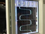
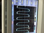
this should be ok right to generate square wave?tomorrow only i going to test as the lab occupied by some other peoples...
 

Ya its correct, but shdnt like approx 0%. it shd like exact 0%... first verify the controller is executes or not after that load this program..
 

Ccpr1l=0 mean 0 right?execute mean can build by mplab or not?i had successfully built
 

That is not full success, can make LED blink on its pin... That is the surety of executing..
 

That is not full success, can make LED blink on its pin... That is the surety of executing..

what you mean by this?

and you said check controller execute or not mean? whether it is malfunction or not?
 

as well as your programming methodologies and circuit connections are correct or not..
 

then how to fully success?circuit connection should not be problem as i checked for few times and i had attached too...

programming methodologies you had verify for me,shouldn't be problem....
 

then load the program and attach the wave form as you did before.. lets see whats happening..
 

i checked the voltage across anode and cathode,i get 353mV if the anode connect to +5v through 68ohm and cathode connect to the collector of transistor and i use camera to see that is no any infrared light.

but when i connect the cathode directly to ground and anode to +5v with 68ohm resistor, it is 1.45v and the led is glowing(which can't see by naked eyes) only can see via phone's camera.

so...?and,i connect the Rc2 to oscilloscope,it show the same waveform as i attached yesterday.......................
 

post your program and Did you see any variatios in LED voltage when connected with transistor (it seems to be working)... Do this simple exprmnt instead of RC2 connect the base resistor to Vcc and check The voltages.....
 

I get this wave on rc2, I initialise the rc2 in main program,otherwise it doesn't work.will try on Monday what's te voltage on base if direct connect to Vcc...
 

Attachments

  • image.jpg
    image.jpg
    2.6 MB · Views: 60
  • image.jpg
    image.jpg
    2.2 MB · Views: 64

not only on the base as well as LED and transistor points. congrats for squarewave, next time put it in DC coupling mode...
 

it is in DC, the option is chosen wrongly, i connect CH1 nut the option shown CH2,haha.

1 more thing to tell,i check the receiver with oscilloscope,it is always 5v,that mean LED doesn't glow?right?

you mean connect base of transistor with resistor to Vcc?i had check the voltage across collector(5v),base(some mV) and emiter(near to 0V) =.="
 

Then you have the problem with transistor... I am giving you some alteration.......

- - - Updated - - -

untitled.JPG Try any one of the configuration..........
 

i think the receiver working right?it is always 5v, then i need to change transistor?for fast switching purpose to support about 38khz-40khz...

without the transistor,how to drive the ir led?because the sink/source current only 25mA for PIC, for my ir led need at least 50mA right?
 
Last edited:

Hey its not working in DC itself...

for a 650mV in Base and with your 3.3k the Collector Voltage should be less than 1 for giving 5V through resistor..
 

Ib=Ic/hfe
Ic=50mA
hfe=40
Ib=0.05/40=1.25mA

Rb=V/Ib=(5-0.7)/1.25m=3440ohm

i take 3300ohm,so the Ib will be 1.3mA.
Ic=1.3mAx40=52mA

what are the thing wont work with DC itself?i need 650mV in base????
 

excellent calculations but by this the collector voltage shd be less than 1 when giving 5v in base... Isnt??
 

the collector voltage should be 1.4-1.6 right?why less than 1?that is why i get about 350mV across anode and cathode?

i'm not sure as i very weak in transistor...

i'm getting some mV on base,and about 5V on collector, base of transistor is connected to RC2, it will feed at 5v at base since i feed 5v to mcu??
 

Here the transistor is working as a switch... in this operation if 5 V applied on the base it will switch ON so that cathode of LED can get nearly gnd (so that it can glow with 1.5 V)... if the 0v is given on the base it will be switched off ans as you said 5V will be on the collector.. so that cathode is disconnected from gnd no GLW. when you are giving square wave this works very fast and half the time the LED will ON as well as oFF so that the voltage may vary but not 5 V on collector at all... you better try the circuits i given.. they will work the same as the transistor circuit work...
 

Status
Not open for further replies.

Part and Inventory Search

Welcome to EDABoard.com

Sponsor

Back
Top