Venkadesh_M
Advanced Member level 4
- Joined
- Jun 26, 2013
- Messages
- 1,374
- Helped
- 258
- Reputation
- 516
- Reaction score
- 254
- Trophy points
- 1,363
- Location
- Coimbatore, India
- Activity points
- 8,019
Code:
while(1)
{
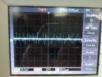
generate_square(); // in 38 khz
delay_ms(120);
output_low(); // IR led in Off state
delay_ms(380); // 380+120 = 500ms period
}- - - Updated - - -
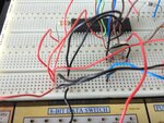
use this procedure to generate square wave...
Now look at the recevier output oFF time that matters with distance.....
that can be found easily
- - - Updated - - -
Code:
while(1)
{
for( i = 0 ; recieve == 0; i++) // Count for number of ms the output is low
delay_ms(1);                        // i is the distance ouput  may be for 1m i = 75; 1.5m i = 25;

while(recieve == 1);
}
- - - Updated - - -
They are not meant to change the duty cycle, They are meant to set a constant square wave for some time.....