Continue to Site

Welcome to EDAboard.com

Welcome to our site! EDAboard.com is an international Electronics Discussion Forum focused on EDA software, circuits, schematics, books, theory, papers, asic, pld, 8051, DSP, Network, RF, Analog Design, PCB, Service Manuals... and a whole lot more! To participate you need to register. Registration is free. Click here to register now.

selecting proper NTC thermistor for limiting INRUSH CURRENT

Status
Not open for further replies.

speedEC

Full Member level 6
Joined
Apr 1, 2011
Messages
337
Helped
23
Reputation
46
Reaction score
21
Trophy points
1,298
Activity points
4,324
Dear all,

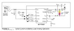
I need your help on selecting proper NTC THERMISTOR for our device to limit the inrush current. I have used 3.7v Li_ion Battery to power our device. I like to add NTC thermistor to limit the INRUSH CURRENT when the device is ON. I have tested using fixed 1.7 ohm resistor for limiting inrush current. It works fine. If I increased to 5.5 ohm resistor, the GSM Module won't register on Mobile Network because of insufficient current supply, I hope.

I give you brief details about the loads I used in our device and its voltage range.
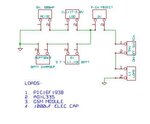
LOADS:

1. SIM900B GSM Module - 3.2v to 4.8v (22 mA - operating current, idle - 1.5mA)

***Please note that it requires 2A (milliseconds period) when transmit burst happens (i.e. while voice/data transmission)

2. 1000uF Electrolitic Capacitor for suppling 2A to Module.

3. PIC MCU

4. ADXL335 SENSOR

Kindly help me on selecting proper NTC THERMISTOR to use in our device to limit the initial Inrush Current.

thank you
 

Looks like a bad idea from the start.

- NTC won't work according to the large current dynamic.
- A fixed resistor can work but will involve increased battery consumption, because the GSM module will compensate lower supply voltage with increased current, at least during transmit.
- If you actually need inrush current limitation (I don't think that it's used by commercial GSM products, but may be you know better), an active current limiter with low resistance shunt, current sense amplifier and MOSFET should work.
 
I suppose the only place where you may need an inrush current limit is between the battery and the reservoir capacitor of 1000uF. Depending on the internal resistance of the capacitor there may be overcurrents at startup. In normal use I would think the idea of a NTC resistor in the power supply line is neither good not necessary. If you select a capacitor with an internal resistance of some hundred milliohms you should be good.
 
A fixed resistor can work but will involve increased battery consumption,...
Yes. Increased battery consumption is a big problem for me. Without current limit resistor, I can able to run the device (GSM in Idle status - 1.5mA) for at least 8 to 9 days (practically). Actually, it should work for 16 days at least (theoretically). For example, 800mA (BATT CAPACITY)/(1.5mA + 0.5mA (Sensor) + 0.5mA (PIC MCU) = 800mA /2mA = 400hrs / 24hrs = 16.6 days. I can able to utilize only 56% of the Battery Full capacity. When I measured the current consumption on the device, it shows 4mA consumes by device. I am working to check where the remaining power goes.

If you actually need inrush current limitation (I don't think that it's used by commercial GSM products, but may be you know better)
I have a doubt here as you mentioned. I have a separate GSM Modem on my hand. No current limit circuit I found on that. But, like to know should we use inrush current limit circuit in our low voltage device?
...an active current limiter with low resistance shunt, current sense amplifier and MOSFET should work...
I have attached a rough circuit for your reference. Battery current coming through p-channel MOSFET (Q1). Pl send your opinion.


I suppose the only place where you may need an inrush current limit is between the battery and the reservoir capacitor of 1000uF
Yes. Correct. This is the only concern for me.
If you select a capacitor with an internal resistance of some hundred milliohms you should be good...
1000uF - 6.3V, 20%, ELECTROLYTIC CAPACITOR - PCE3855CT-ND (www.digikey.com) digi-key part-id: I can't see internal resistance of the CAP.
 

Attachments

  • INRUSH_CURRENT_CIRC.jpg
    INRUSH_CURRENT_CIRC.jpg
    14 KB · Views: 114
  • 1000uF_CAP_DATASHEET.pdf
    291 KB · Views: 94
  • loadSharingCircuit.JPG
    loadSharingCircuit.JPG
    42.1 KB · Views: 112

I don't think that a current limiter is needed. A discharged capacitor will be strained with a short inrush current when connecting to the battery. That's a common situation for electrolytic capacitors in power supplies and no problem.
 
Thanks for providing timely help.

Edit: one more clarification. Should we discharge the capacitor (using resistor) after turn-off the device? What could be the effect of remaining voltage & current of capacitor after turn-off the device, if not fully discharged? That is, will this affect other components in the circuit, if not discharged the capacitor fully before turn-on the device again.

When I tested the remaining voltage on Capacitor (1000uF), it comes down to around 1.5 volts in 2 seconds. So, all IC components in the circuit will be off. No problem. What I want to know is, whether the remaining voltage and current will damage other components in the circuit, if not fully discharged before turn it on the device again.

NOTE: As this is a battery powered device, as you said, current consumption is critical for me. But, all standard practice must be employed to protect the circuit.

waiting for your reply.

thanks
 
Last edited:

Status
Not open for further replies.

Part and Inventory Search

Welcome to EDABoard.com

Sponsor

Back
Top