phongphanp
Full Member level 5
You may use try this circuit :

For adjust Vsupply form power supply.
For adjust Vsupply form power supply.
Follow along with the video below to see how to install our site as a web app on your home screen.
Note: This feature may not be available in some browsers.
hello !This should be a duplicate of the last stage of your layout.
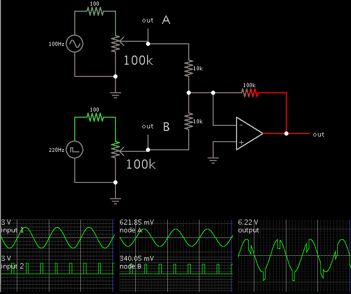
This simulator (www.falstad.com/circuit) does not show supply leads. It only has a setting for output V min and max. The output occupies the same range as if supply leads were shown.
I wonder about your supply V settings at the third op amp.
Did you try various high and low input levels? At both potentiometers?
Something should have worked. You should have seen some signal from the output.
- - - Updated - - -
This should be a duplicate of the last stage of your layout.
This simulator (www.falstad.com/circuit) does not show supply leads. It only has a setting for output V min and max. The output occupies the same range as if supply leads were shown.
I wonder about your supply V settings at the third op amp.
Did you try various high and low input levels? At both potentiometers?
Something should have worked. You should have seen some signal from the output.
")
hello !You need to plug a stereo patch cable into your computer. A common type is the 1/8 inch 'mini' size.
Typical cable like you would buy at the store for a few dollars. (Or on Ebay.)
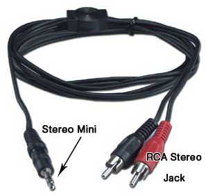
Or identical plug at both ends:
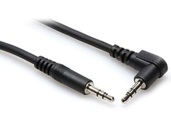
The other end can go to a matching mini jack, installed in your project enclosure. Then connect wires from the jack to your circuit board.
Or if you would rather make a permanent connection, just clip the plug(s) off one end, run the cable into your enclosure, and solder the wires directly to your circuit board.
Well, before any further discussion, why would you like to implement it using MCU? I lost my interest in the project coz it actually is much better in its analog form, also its digital version will need more processing power.
its all fine..You must design new value of resistor to your circuit ,step by step, by using formular form circuit analysis not only approximated value because such a ideal model of Opamps used
(refer to books your bookshelf). What is impedance of audio stereo cable ? You know this ?
Ask your self, How to check that impedance of headphone ? I think from output 2 Volts peak-peak above refered by you , you can use the voltage divider method to find the
impedance at output branch of your circuit. And should read my above old hints again.
That is the basic analysis but may hard for newbie like other subjects to familiar and study all thing that you can think/find !!!!!!!!!
Happy ;-)
but point is, either i must have to use a jack sort of thing to make connection with bread board..??? if so then which jack i have to use?? or i use audio line cable directly connected to breadboard.?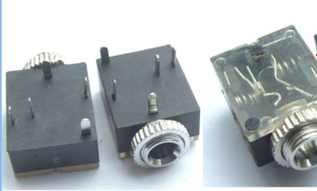
good !A stereo 'mini' (1/8 inch) jack is typical.
Though you may be able to attach alligator clip leads to the barrel rings on the plug...
it is all too easy for them to slip, causing crackling in your ears, or a short circuit, etc.
- - - Updated - - -
A stereo 'mini' (1/8 inch) jack is typical.
Though you may be able to attach alligator clip leads to the barrel rings on the plug...
it is all too easy for them to slip, causing crackling in your ears, or a short circuit, etc.
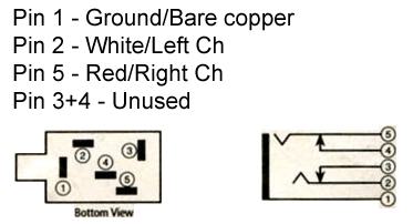
As it stands, you'll use only 3 terminals: Left ch., right ch., ground.
The other two pins are for external speakers. They disconnect when you insert the headphone plug. (You can spot the springy clips in the righthand image.)
Typical schematic:
- - - Updated - - -
As it stands, you'll use only 3 terminals: Left ch., right ch., ground.
The other two pins are for external speakers. They disconnect when you insert the headphone plug. (You can spot the springy clips in the righthand image.)
Typical schematic:
oh nope i am talking about its implementation in real life.. how i have to connect this ANC circuit with headphones..?? how i gave input.? how i take out put??Try to use Monte Carlo Analysis for adjust your circuit but this function I had found on Pspice program.
The route to be professional has science , but Engineering tend to imitate world.
dear you still dont understandThat's mechanics work , your ANC component be solution of the drop voltage error ? But if you try add ANC spice model to simulation of full system , it's not better ?
And in Pspice program , you can find such a model , I think . But depend on What's requirement quality of your work .
In production process , There're optimizing process could you find it on commercial mechanics part like tunning and , long time ago , software process has meet The standard one.
Implement the circuit on veroboard. Take out and give the signals from/to it as necessary using the stereo jacks and all.
Implement the circuit on veroboard. Take out and give the signals from/to it as necessary using the stereo jacks and all.
what should be the block diagram of active noise cancellation headphones?? it should be either like this
or like this ??
- - - Updated - - -
https://www.google.co.th/search?hl=..._cp.r_qf.&fp=b5bb1c82f21b0af&biw=1600&bih=739
Read Turtorial Optimizing a Design (Passive Terminator) on The book "Microsim Pspice Optimizer" Analog Performance Optimization Software Page 5-1. And I have plan to design Microstrip antena of RFID system by this electronics software,also.
what should be the block diagram of active noise cancellation headphones?? it should be either like this
or like this ??
- - - Updated - - -
As it stands, you'll use only 3 terminals: Left ch., right ch., ground.
The other two pins are for external speakers. They disconnect when you insert the headphone plug. (You can spot the springy clips in the righthand image.)
Typical schematic:
- - - Updated - - -
As it stands, you'll use only 3 terminals: Left ch., right ch., ground.
The other two pins are for external speakers. They disconnect when you insert the headphone plug. (You can spot the springy clips in the righthand image.)
Typical schematic:
what should be the block diagram of active noise cancellation headphones?? it should be either like this
or like this ??
what should be the block diagram of active noise cancellation headphones??
1.
Your first diagram is better. Furthermore the ambient noise goes directly to your ears, rather than going through circuitry.
Therefore the ambient noise arrow should be transferred to the extreme right.
2.
Although the noise can be (1) amplified, and (2) inverted, by a single op amp...
and your second diagram appears to represent an inverting op amp...
The inversion function is distinct from the amplification function, and both are necessary. Therefore your first block diagram conveys the concept more correctly.
I'm afraid I don't know the science of how many microphones to use, or exactly where to position them.
Initially I thought one mic would be sufficient at each ear. I thought it should not be within the earpiece compartment, but outside. I guess I was wrong.
As for your block diagram, it should also show the mic, speaker, and ear. That way the entire theory of operation can be grasped quickly.
If you can assemble this project, and make the noise cancellation work, then you will know more about it than I and a lot of other people.