mtwieg
Advanced Member level 6
So I've been building current mode class D RF amps lately (around 123MHz). Up until now I've been using class E preamps to drive a rough sine wave into those FETs, which works all right, but I know that a square wave would work better. But I haven't thought of a convincing method of producing such a gate drive (without making a custom ASIC anyways). I'm looking for rise/fall times of 3ns or less, no excessive ringing (peak gate voltage must not exceed 6V), and with overall efficiency of 25% or so (about 1W per gate). My starting signal source can be a +10dBm carrier (sine wave) from a 50ohm port, or a 10mA CML clock.
I've been trying things in SPICE, including BJT and MOS push-pull drivers. What I'm finding is that in order to build a fast enough driver stage, I need devices large enough that the input capacitance of the driver is still quite significant, and requires large peak currents to operate properly (like 0.5A or more). So to get from my starting carrier, I would need several driver stages cascaded, and that's just going to be a mess on a PCB...
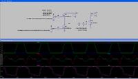
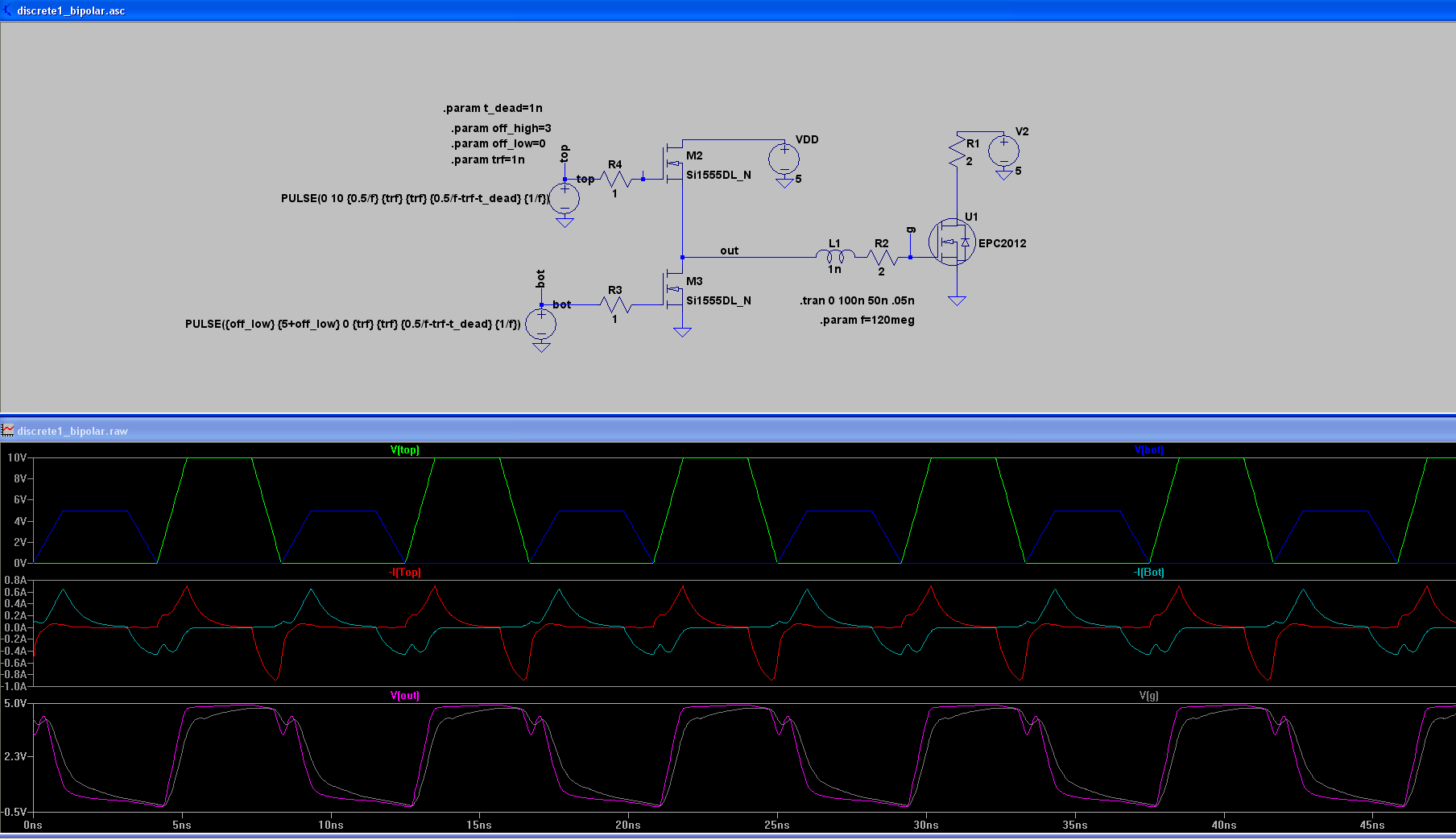
Here's an example of one of the better looking circuits I've come up with (I've found that simplicity works best so far...), using Nmos FETs on the output (meaning I'd need complementary drive signals, with some DC biasing). But even this requires large peak currents from my pulse sources, and I can't come up with a good way to get that from my available signal source.
I was also looking at the possibility of just using a bunch of logic inverters/buffers in parallel, but it seems like the only devices specified for very high speed and drive strength aren't capable of giving near 5V output swing (most are ECL or LVDS transceiver ICs).
Any ideas for me?
I've been trying things in SPICE, including BJT and MOS push-pull drivers. What I'm finding is that in order to build a fast enough driver stage, I need devices large enough that the input capacitance of the driver is still quite significant, and requires large peak currents to operate properly (like 0.5A or more). So to get from my starting carrier, I would need several driver stages cascaded, and that's just going to be a mess on a PCB...
Here's an example of one of the better looking circuits I've come up with (I've found that simplicity works best so far...), using Nmos FETs on the output (meaning I'd need complementary drive signals, with some DC biasing). But even this requires large peak currents from my pulse sources, and I can't come up with a good way to get that from my available signal source.
I was also looking at the possibility of just using a bunch of logic inverters/buffers in parallel, but it seems like the only devices specified for very high speed and drive strength aren't capable of giving near 5V output swing (most are ECL or LVDS transceiver ICs).
Any ideas for me?