Continue to Site

Welcome to EDAboard.com

Welcome to our site! EDAboard.com is an international Electronics Discussion Forum focused on EDA software, circuits, schematics, books, theory, papers, asic, pld, 8051, DSP, Network, RF, Analog Design, PCB, Service Manuals... and a whole lot more! To participate you need to register. Registration is free. Click here to register now.

How to obtain a controlled 5 volts supply from a 6v 4.5ah Rechargeable Battery

Status
Not open for further replies.
kk sir what about the other resistor's unit (330) ?????

any example of TO-220 which is common as per you ? please mention . . cause you did practically so its better to go with that :) thanks

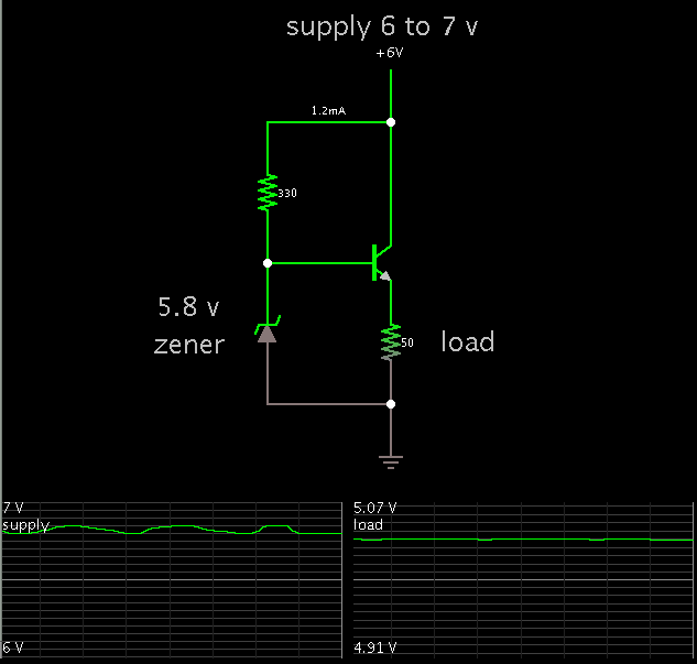
330 ohms is a suitable value... neither too high nor too low... to (a) turn on the zener diode so it will provide regulation, and (b) turn on the transistor sufficiently to power a light load at 5V.

Adjust its value accordingly, so as to avoid wasting milli-amps, and to avoid burning up either the zener or transistor.

The transistor can be a common NPN general-purpose type. Many have 'TIP' prefixes (example, TIP 31).
 

kk so any substitute for this TIP 31 ?


ya that was failed so i started the thread here :)
well sir what is LDO ??????????
 

LDO is low dropout regulator. Can regulate output with small voltage difference between input and output voltage. Example you need exact 3V and you have 3,3V or you need 5V and have 5,5V or 6V.
 

oh ya i have that a lot & i apply this one where the high current matters , but i want to know just like that a common number for TO-220 size , though a lot of number is there but i need a common one . . thanks
 

Three questions:
(1) What type of battery is it? This will determine the voltage profile as the battery discharges.
(2) How much current is required?
(3) Are you Shpongled?
 

MC34063?
Small, cheap, adjustable, short circuit protected solution for dc to dc conversion.
To adjust 5volts, change R3,R4 and VR1.


circuit-battery-voltage-regulator-by-mc34063.jpg
 
Last edited:

Three questions:
(1) What type of battery is it? This will determine the voltage profile as the battery discharges.
(2) How much current is required?
(3) Are you Shpongled?


battery is 6v 4.5 ah & current could be small or large depending on circuitry so i need as much as possible . .

- - - Updated - - -

MC34063?
Small, cheap, adjustable, short circuit protected solution for dc to dc conversion.
To adjust 5volts, change R3,R4 and VR1.


View attachment 88728


oh wowwwww so nice sir thanks for the diagram & details . moreover i hv to make practicals after it :) thanks
well sir is there any substitute too available for this i.c. or its a standard one all around ?
 

Common type. This chip is frequent in dc-dc converters. For example: willem eeprom reader/writer voltage synth.
Low dropout and high efficiency. Better than a zener+transistor based stabilisator. :)
It work with/without external transistor.
 

This is a simple 5V regulator using a transistor, and zener diode or suitable voltage reference.


thanks sir this circuit is working very efficiently & i applied in all my designs & practice thats why this one is spreading out its branch in several applications , but now i need same with 12 volts supply as original source . .

Too here i need sources range from 3v to 9v i mean 3v 4v 5v 6v 9v . . so please tell what extra components i need ?
& what changes further i ve to make in original one . . thanks please comment
 

You can install a potentiometer across the zener. Dial it to a position which yields your desired output V. It will be regulated for all loads less than a fraction of an ampere.

Voltage will start to drop if you draw too much current.

My simulation shows the potentiometer dialed to the upper extreme. With a 9.6 or 9.7 V zener, you should get 9 V output V. When you dial the pot to the lower extreme, you should get 3 V.

3856053300_1385441316.png


To obtain more current, you may need to increase the bias, by reducing the value of resistors in the bias network.

You should use a transistor rated for the amount of power that it will dissipate in the worst case.


hmm just wow !

what doer it mean actually sir " It will be regulated for all loads less than a fraction of an ampere"

Too refer me most commonly available transistor rated for amount of power

Whats the value of pot.near load or output you shown in diagram sir ????

&

As you shown a 6.8 mA line so what if the current rate is 1 Amp. from the source ?????????????
 

hmm just wow !

what doer it mean actually sir " It will be regulated for all loads less than a fraction of an ampere"

With lighter loads, voltage regulation will be better (within a tighter range). As you draw more current, regulation gets worse, and your output voltage will fluctuate more. This is just a simple regulator, and it does not perform as well as more complex circuits.

It will require some experimentation with component values, so you can have the range of adjustment which you desire.

Too refer me most commonly available transistor rated for amount of power

Whats the value of pot.near load or output you shown in diagram sir ????

&

As you shown a 6.8 mA line so what if the current rate is 1 Amp. from the source ?????????????

Then you want a more robust transistor. My homemade power supply uses a 2N3055 (TO-3 package). Inexpensive. Commonly available. My supply can provide over 3 A, at several volts. In those situations the 2N3055 gets too hot to touch (even though I heatsink it to the steel enclosure). It has not failed in 30 years.

Your load will be 9 ohms, if you draw 1A at 9V.
Your transistor will need a sufficient bias current. Or else you can use a darlington arrangement, or mosfet, etc.

To show that the load is variable, my simulation has a potentiometer. (50 ohm)


With lighter loads, voltage regulation will be better (within a tighter range). As you draw more current, regulation gets worse, and your output voltage will fluctuate more. This is just a simple regulator, and it does not perform as well as more complex circuits.

It will require some experimentation with component values, so you can have the range of adjustment which you desire.


Then you want a more robust transistor. My homemade power supply uses a 2N3055 (TO-3 package). Inexpensive. Commonly available. My supply can provide over 3 A, at several volts. In those situations the 2N3055 gets too hot to touch (even though I heatsink it to the steel enclosure). It has not failed in 30 years.

Your load will be 9 ohms, if you draw 1A at 9V.
Your transistor will need a sufficient bias current. Or else you can use a darlington arrangement, or mosfet, etc.

To show that the load is variable, my simulation has a potentiometer. (50 ohm)


ha ha ha ya ya same here sir , i make practicals & lost a bc 547 & a bd 139 & before your last comment here i tried & connected 2N3055 & what you explained above,i got the same,now the problem is totally fixed out & ya it gets heated with higher currents of sure . . well i was getting 3.5 volts minimum with 1.5k in series with 2k at base junction , i replaced it with 1k now getting much better results , too i connected 100k from emmiter to earth in place of a pot., that one is working fine , infact when i am writing this explanation here , the whole system is working in front of me , i dialed preset to 5 volts & & connected a PWM ckt.to drive a motor with desird speed . . This one is amazingly working . .

But i ve to go through your newly designed , but one thing i can say that for normal ic or transistor ckts. where power consumptionn is not much , a simple BJT is ok . . so as to manage space & cost . . thanks thanks thanks a lot sir . . any more suggestions ?
 

You can install a potentiometer across the zener. Dial it to a position which yields your desired output V. It will be regulated for all loads less than a fraction of an ampere.

Voltage will start to drop if you draw too much current.

My simulation shows the potentiometer dialed to the upper extreme. With a 9.6 or 9.7 V zener, you should get 9 V output V. When you dial the pot to the lower extreme, you should get 3 V.

3856053300_1385441316.png


To obtain more current, you may need to increase the bias, by reducing the value of resistors in the bias network.

You should use a transistor rated for the amount of power that it will dissipate in the worst case.


sir for now this diagram is working very smoothly for 3 to 9 volts , now please what changes i ve to make on the above circuit if i am selecting a new range of 3v to 12 volts ??

i ve 12 volts zener for now which i connected in the same circuit already but not getting higher value more than 10 volts

please help
 

If you want the maximum output V, then you need to toss out the zener diode. Just use the potentiometer to adjust the voltage.

It is not the same as a regulated supply. However if your power source is regulated to 12V then that will have to be good enough.

The maximum voltage you'll get is about 11.3 V. (The 0.6V drop is drop through the NPN bias).

This is similar to the way I constructed my own power supply. It is unregulated. If I draw more than a couple amperes, the voltage sags.

5640872600_1386013677.png


What if we were to put the load in the collector leg? We could get 12V in that case. However the large range of adjustment would be lost. It would want to act more like a current source.
 

Status
Not open for further replies.

Part and Inventory Search

Welcome to EDABoard.com

Sponsor

Back
Top