Continue to Site

Welcome to EDAboard.com

Welcome to our site! EDAboard.com is an international Electronics Discussion Forum focused on EDA software, circuits, schematics, books, theory, papers, asic, pld, 8051, DSP, Network, RF, Analog Design, PCB, Service Manuals... and a whole lot more! To participate you need to register. Registration is free. Click here to register now.

[SOLVED] h bridge boost charging at constant current.

Status
Not open for further replies.

israel7732

Member level 3
Joined
May 2, 2010
Messages
66
Helped
6
Reputation
12
Reaction score
5
Trophy points
1,288
Location
Nigeria
Activity points
1,668
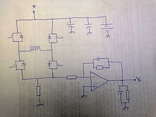
hi. i was told that an h-bridge could be used to boost charge inverter battery at constant current by varying the duty cycle of pulsing the bottom two mosfets. please how could the the charging current be measured and used as a feed back to the micro controller.
 

Typically DC current is measured by installing a sense resistor somewhere in the power loop.

The resistor is a low value, often a fraction of an ohm. The idea is for it not to restrict current, but rather to generate a small voltage across it.

This voltage is amplified as required.

Then it is fed to a control/measuring device.

If the current flow is large, then it may not be preferable to insert a resistance in the power loop. It becomes feasible to use magnetic sensors which use the hall effect, etc.
 

thanks. my design is for a sine wave inverter. please, can you give the part number of a magnetic type sensor. i would not like to use a resistor. thanks
 

Try an internet search on 'hall effect sensor'.

You'll need to determine what current range you want to measure, whether you want a complete coil-combined-with-sensor, or a simple $1 device, etc.

There are also hall effect switches as well. A hall sensor provides varying voltage output. A hall switch provides one of two states.
 

Thanks for your assistances. Do you know how the h bridge boost charging is done?

- - - Updated - - -

Thanks for your assistances. Do you know how the h bridge boost charging is done?
 

Thanks for your assistances. Do you know how the h bridge boost charging is done?

It's not clear what you are planning. You have mentioned a sine-wave inverter, charging, charging current, and boost charging.

This sounds like a complex project, requiring several stages, and knowledge about the principles of operation.

Can you describe what power supply you are starting with, and what sort of load the power is going to?
 

While charging, the upper 2 MOSFETs act as diodes (using the internal body diode). The bottom 2 MOSFETs are PWM-ed and form a boost converter along with the transformer, the output of which, charges the battery.
 
Thanks for your comment tamid. The sine wave inverter part is completed and tested ok. What i intend to do is to implement the charging method u described above. My transformer is 230v to 8v. When the mains is connected to the high voltage side of the transformer the voltage at the low voltage side is below 10v and could not charge my 12v battery. So, i need to boost the voltage.

- - - Updated - - -

Am aware that the upper mosfets are to be kept off. Are the bottom two mosfets to be switched on at the same time and off at the same time? Please specify what frequency to use and the maximum duty cycle. Is the transformer's inductance to be considered? If there are any formulas please share.
 

Yes, the bottom two MOSFETs are to be switched on and off simultaneously. Frequency is up to you. Duty cycle will determine voltage. Think of it as a boost converter. So, Vo = Vi/(1-D), Vo- Output voltage, Vi- Input voltage, D - Duty cycle. Then, consider the losses and voltage drops.

The algorithm could be:
Check battery voltage. If <13.5V (adjust as required), start PWM. Keep on increasing duty cycle until required charging current is passing. Check battery voltage and duty cycle and increase duty cycle if charging current is to be increased and decrease duty cycle if charging current is to be decreased.
Check battery voltage. If >= 13.5V (adjust as required), either stop PWM, or lower charging current (depending on you).

Hope this helps.
Tahmid.
 
Setting a constant (or slowly variable by charge current controller) duty cycle results in low power factor, but is probably sufficient for basic applications.

Ultimately you would implement PFC like PWM control. Synchronous switching is an option to increase the efficiency.
 

Thanks tahmid. Could you sketch where and how to monitor charging current.
 

Use a shunt for current measurement. Connect it between the source of the bottom MOSFETs and ground. Since the battery is being charged, with respect to battery ground, the voltage at the source will be negative (as microcontroller VSS is battery ground). So, use an inverting amplifier, employing a single supply operational amplifier. The output of this goes to the microcontroller.

Hope this helps.
Tahmid.
 

    thannara123

    Points: 2
    Helpful Answer Positive Rating
I don't see a purpose for a rectifier. You want to measure the average value of the DC bus current.
 

I hope this is okay? Thanks for your concern.
0_1345100015.png
 

thanks israel

please can you provide values for the circuit and what is the gain or amplification of the opamp config

thanks
 

circuit values depend on your application. just make sure the current sense resistor doesn't waste too much power. use V=IR and P=I*IR. amplification now depend on what voltage output you want from the opamp at a given sense current.
 

Status
Not open for further replies.

Similar threads

Part and Inventory Search

Welcome to EDABoard.com

Sponsor

Back
Top