Continue to Site

Welcome to EDAboard.com

Welcome to our site! EDAboard.com is an international Electronics Discussion Forum focused on EDA software, circuits, schematics, books, theory, papers, asic, pld, 8051, DSP, Network, RF, Analog Design, PCB, Service Manuals... and a whole lot more! To participate you need to register. Registration is free. Click here to register now.

How to find Rs and Cs for 2nd order RC circuit

Status
Not open for further replies.

Lonari

Newbie level 6
Joined
Jul 8, 2012
Messages
12
Helped
1
Reputation
2
Reaction score
1
Trophy points
1,283
Activity points
1,394
Hi guys,
I need to design a low pass filter with a cuttoff frequency of approx 5kHz. Problem is that it must have a -40dB/decade roll-off rate. So it has to be second order.

I can do f_c= 1/2*pi*RC
R=330 Ohms
C=0.1 uF
to get the first order filter with approximately 4800Hz cuttoff freq.

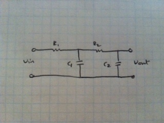
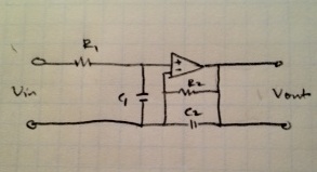
I believe a second order will give -40dB/decade? how do I go about doing this? I believe the equation for the second order is fc=1/2*pi*sqrt(r1*c1*r2*c2); No sure how to find the Rs and the Cs for this. Thanks in advance!
 

Re: 2nd Order RC Circuit

for a specific frequency u can randomly pick the value of resistor and capacitor
only thing matter the confriguraion you chose
the decay rate depends upon the value of Q...
consult this book
filter design by m.e van valkenburg
 

Re: 2nd Order RC Circuit

I can't randomly pick the RC values I have a set cutoff frequency and roll-off rate that I need to get out of my circuit :(
You already calculated the values for the first RC:
R1=330 Ohms
C1=0.1 uF

Now you just add a second RC after that. The time constant should be the same, but the impedances should be higher so that the second RC filter doesn't load the first one too much.
You could use:
R2=3.3K
C2=0.01uF
 

Re: 2nd Order RC Circuit

Sorry guys, but up to now there was no correct answer:
* The document proposed by fareen is good for active filters ony. However, as far as I understood Lonari he wants a 2nd order passive filter. More than that, it is NOT true that the decay rate depends on the Q value. The decay rate (roll-off) depend on the filter degree only. Each 2nd order lowpass has a slope of -40 dB/dec.
* Godfreyl's calculation with two equal time constants is not correct as it would lead at 4.8 kHz to an attenuation of -6 dB instead of -3 dB.
* Lonari, you have three alternatives:
1.) Two RC sections T1=R1C1 and T2=R2C2 (directly coupled): H(s)=1/D(s) with D(s)=1+s(T1+T2*R1C2) + s^2*T1T2
2.) Two equal RC sections T1=T2=T with a unity gain buffer in between: H(s)=1/D(s) with D(s)=(1+sT)^2.
3.) Usage of an active 2nd-order filter (as contained in the document mentioned by fareen).

Before fixing any values you have to select one of these alternatives.

- - - Updated - - -

Remark to 2.): In this case, the 3dB frequency can be calculated as w(3dB)=0.8/T
Remark to 3.): Using an active RC filter you have the choice between several different filter characteristics (Butterworth, Bessel,...)
Remark to 1.) As an approximation, you can use the formula as given above under 2.) - provided you perform an impedance scaling for both equal time constants as described by godfreyl in post#5.
Otherwise, for R1=R2 and C1=C2 the calculation of the 3dB frequency is rather involved (please note such a filter has very poor damping characteristics) .

Correction to 2.): w(3dB)=SQRT(1.414-1)/T=0.643/T.
 
Last edited:
Re: 2nd Order RC Circuit

Thanks a lot guys!
I think I kinda got it:
Here is my code: (I went with the 1st choice).

clc;
clear;
R1=330;
R2=3300;
C1=0.1*10^-6;
C2=0.01*10^-6;
fc=1/(2*pi*sqrt(R1*C1*R2*C2))

num= 1/(R1*R2*C1*C2);
den= [1 ((1/(R1*C1))+(1/(R2*C1))+(1/(R2*C2))) (1/(R1*R2*C1*C2))];
sys= tf(num,den)
bode(sys)

It's matlab code, its pretty easy to understand I think.
Is this correct? Attached is the circuit image.
46_1341781040.jpg


All I require is for it to cuttoff frequencies above 5kHz and have a roll-off of -40dB.
 

Re: 2nd Order RC Circuit

Thanks a lot guys!
I think I kinda got it:

I am not quite sure about it. The 3dB frequency of your circuit is at 3 kHz (see my formula in post #6, remark to 1).
 
Re: 2nd Order RC Circuit

The corner frequency is about 5KHz, but Q is close to 0.5, so it's -6dB at the corner frequency. I assumed the requirement was to have the corner frequency at 5KHz, not the -3dB point. Anyway the response is -40dB at 50KHz. If he wants -3dB at 5KHz then I agree the component values must be changed.
 

Re: 2nd Order RC Circuit

Thanks a lot guys!
I think I kinda got it:
Here is my code: (I went with the 1st choice).

clc;
clear;
R1=330;
R2=3300;
C1=0.1*10^-6;
C2=0.01*10^-6;
fc=1/(2*pi*sqrt(R1*C1*R2*C2))

num= 1/(R1*R2*C1*C2);
den= [1 ((1/(R1*C1))+(1/(R2*C1))+(1/(R2*C2))) (1/(R1*R2*C1*C2))];
sys= tf(num,den)
bode(sys)

It's matlab code, its pretty easy to understand I think.
Is this correct? Attached is the circuit image.
46_1341781040.jpg


All I require is for it to cuttoff frequencies above 5kHz and have a roll-off of -40dB.


Hey Lonari,

You need to add a unity gain buffer or unity gain Op-amp or so between the two filters. Else it wont be a 2nd order filter. It gives very weird results without the buffer!
 

Re: 2nd Order RC Circuit

I have no idea how to add a unity gain op-amp or how to add that into my calculations to find the transfer function :(
 

Re: 2nd Order RC Circuit

I have no idea how to add a unity gain op-amp or how to add that into my calculations to find the transfer function :(

Unity Gain = amplification x 1

We use the buffer to isolate the first signal from the second (Due to the high input impedance of the buffer) and prevent interference between the two. Once we get the output of the first signal (from the buffer) we can cascade it with the same second Low pass filter. and it all works fine

Now the reason we do it is because of the parallel networks involved. A Low pass is effectively a voltage divider. so if we look across the first capacitor we find that the impedance is formed not by the capacitor alone but the capacitor and a low pass filter in parallel. So it behaves, I hope this helps.

For a buffer you can use any opamp with a unity negative feedback (connect the negative input pin with the output and feed the signal into the positive pin)

Op-Amps: CA3130, TL082, LM741, etc...

Hope it helps

Cheers
K
 

Re: 2nd Order RC Circuit

Unity Gain = amplification x 1

We use the buffer to isolate the first signal from the second (Due to the high input impedance of the buffer) and prevent interference between the two. Once we get the output of the first signal (from the buffer) we can cascade it with the same second Low pass filter. and it all works fine

Now the reason we do it is because of the parallel networks involved. A Low pass is effectively a voltage divider. so if we look across the first capacitor we find that the impedance is formed not by the capacitor alone but the capacitor and a low pass filter in parallel. So it behaves, I hope this helps.

For a buffer you can use any opamp with a unity negative feedback (connect the negative input pin with the output and feed the signal into the positive pin)

Op-Amps: CA3130, TL082, LM741, etc...

Hope it helps

Cheers
K

Would this work?
29_1341804393.jpg


Also, does it affect my calculations on matlab I posted above? That is to find the transfer function and the bode plot?
 

Re: 2nd Order RC Circuit

Would this work?
29_1341804393.jpg


Also, does it affect my calculations on matlab I posted above? That is to find the transfer function and the bode plot?

The above circuit would just give you a positive rail on the output and the capacitor is across ground and thats something I havent seen before. But it blocks any DC current return. So it probably wont work.

I am attaching a schematic here. Check it out

View attachment LPF II.pdf

This should works. If you use this you dont have to alter your MATLAB Transfer function

Cheers
K

- - - Updated - - -

also in MATLAB the transfer function should be

t1 = C1R1; t2 = C2R2;

num = [ 1/(t1*t2) ];
den = [ 1 (1/t1 + 1/t2) 1/(t1*t2) ];

hope it helps

Cheers
K
 

Re: 2nd Order RC Circuit

Lonari, as mentioned in my post#6 you do not need a unity gain buffer if you are using the component dimensioning according to remark 1) with the correction factor 0.643.
That means: Reduce your resistors or capacitors by a factor 0.643 and you will arrive at a 3dB frequency of approx. 5 kHz.

LvW
 
Last edited:

Re: 2nd Order RC Circuit

For comparison and contrast, here is a link to an animated simulation.

It includes
(1) the 2nd order filter with cap values .1 uF and .064 uF (per LvW post #15)
(2) 1st order filter
(3) plain resistor.
Also a triple oscilloscope trace showing frequency sweep from 150 Hz to 15k.

Click the link to open the falstad.com website. Click Okay to allow the connection.

To change component values, press ctrl or alt key, and click the component.

https://www.falstad.com/circuit/#$+...25E-5+0+-1 o+13+64+0+34+5.0+9.765625E-5+0+-1
 
Re: 2nd Order RC Circuit

Hi BradtheRad,
I didn't check the animation in detail (although I still have some problems to see what I can gain from it) - however, I have the feeling that the shown dimensioning does not follow the "decoupling rule" (which is the basis for the mentioned factor of 0.64): The second RC unit must not load the first RC unit (better: only negligible). That means: Equal time constants but with R2>10*R1.
Or did I misunderstand something?

LvW
 

Re: 2nd Order RC Circuit

I didn't check the animation in detail (although I still have some problems to see what I can gain from it) - however, I have the feeling that the shown dimensioning does not follow the "decoupling rule" (which is the basis for the mentioned factor of 0.64): The second RC unit must not load the first RC unit (better: only negligible). That means: Equal time constants but with R2>10*R1.
Or did I misunderstand something?

LvW

I'm going on a hunch that the problem was given originally to demonstrate that higher orders of filters are not constructed simply by adding a duplicate stage of the first-order filter. It needs deeper examination.

Right away we realize one stage alters the time constant on the other.

This is a link to an article telling about the problem of adding an identical second stage. The corner frequency is altered (I believe you introduced this idea in post #6). It derives equations for calculating the values of the 2 resistors and 2 capacitors.

https://www.johnhearfield.com/RC/RC4.htm

Also informative are:

https://www.electronics-tutorials.ws/filter/filter_2.html


I constructed three simulations to show whether the schematic by Lonari (post #7) is on the right track.

His rolloff curve is indeed steeper than that for a first order.

We can also see that the loading effect does not make the signal disappear altogether... even if the second stage has similar values as the first stage.

It's an advantage to use an animated simulator, because we can simulataneously compare current flows, phase differences in current flow, frequency sweeps, effects of altering component values, etc.

And now I realize I should have noticed that the .64 factor is the amount to reduce by. The second capacitor should be .036 uF.
 

Re: 2nd Order RC Circuit

Right away we realize one stage alters the time constant on the other.

This is a link to an article telling about the problem of adding an identical second stage. The corner frequency is altered (I believe you introduced this idea in post #6). It derives equations for calculating the values of the 2 resistors and 2 capacitors.

https://www.johnhearfield.com/RC/RC4.htm

Hi BradtheRad, I know - perhaps I am "pedantic", but I think we shouldn't say that "one stage alters the time constant on the other.".
For my opinion, there is no isolated "stage" with a particular time constant. Instead, we simply have a two-pole network. But, of course, I know what you mean.
More than that, a first short look on the first of the documents referenced by you (johnheartfield) has revealed some points which deserve some comments.
Did you already examine the paper in detail?
I do not agree with all of his conclusions - in particular that the maximum Q of the circuit topology shown is approx. 0.3.
May be, I'll come back to this document somewhat later.
Thank you.
LvW
 

Status
Not open for further replies.

Similar threads

Part and Inventory Search

Welcome to EDABoard.com

Sponsor

Back
Top