Olamide2nd
Junior Member level 2
Goodmorning friends,am waiting for your updates.
Follow along with the video below to see how to install our site as a web app on your home screen.
Note: This feature may not be available in some browsers.
good day esteemed members of the forum
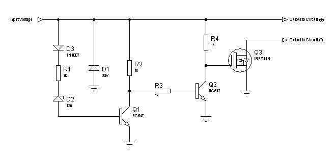
pls can someone help me with a circuit diagram for a 1000 watt pure sin wave inverter pls
thankyou in advance