Continue to Site

Welcome to EDAboard.com

Welcome to our site! EDAboard.com is an international Electronics Discussion Forum focused on EDA software, circuits, schematics, books, theory, papers, asic, pld, 8051, DSP, Network, RF, Analog Design, PCB, Service Manuals... and a whole lot more! To participate you need to register. Registration is free. Click here to register now.

[SOLVED] 9 V and 5 V UPS + battery monitoring

Status
Not open for further replies.
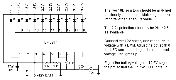
Nice to know that you managed to get an LM3914. I had already designed a circuit using two LM339 comparator ICs, but the LM3914 design is more compact. Don't worry about the N suffix. Popular ICs are often made in many different packages, temperature range, etc. The N simply denotes that particular type of plastic package. Such suffixes are often omitted in schematics and discussions.


The battery is connected to the UPS as in the schematic. The monitoring circuit is connected to the battery as in the schematic. That is, the battery is connected to both the UPS and the monitor circuit at the same time. The "+12V BATT" terminal at the bottom of the schematic goes to the battery and serves as both the power supply and the voltage sensing point. This is shown in the diagram below which shows parts of the UPS and the monitor circuits -

28_1325935729.png


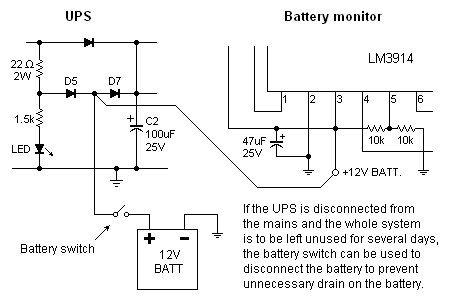
There is no 2.2 ohm resistor in the UPS circuit. It's 22 ohms. Yes, it's OK to use a 5W resistor, and wirewound is fine too. All other resistors are 1/4W. It's OK to use higher wattages, the only difference being that they will be bigger and more expensive.

If you're still not clear about something, just ask again.

Sirs,

The UPS circuit is successful, thank you so much sirs!

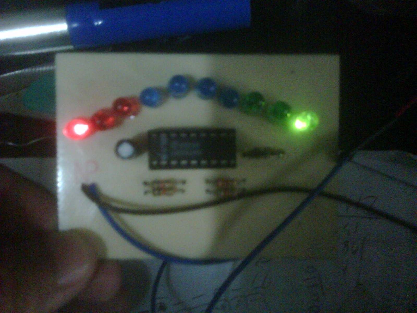
I did the battery monitoring sirs, but none of the LEDs are on. when i connected to the battery directly, same goes with the circuit just like on the picture above. I did test some readings on the battery monitoring circuit but theres no reading at all on the LED copper, yet there is 12 V input on the circuit.

Here's our schematic sirs.


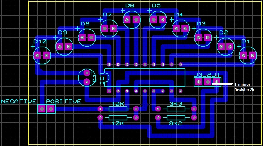
please sirs, have a look on it
 

The led's (and a capacitor) all connect to a trace marked '+'. However the positive supply is not connected to the trace.

You'll have it operating soon.
 
Sir brad,

That explains all, thank you so much. I was having a hard time to troubleshoot this, why i didnt see that. that solves the problem sir. ill be on it and report back. for a while..

---------- Post added at 07:18 ---------- Previous post was at 06:50 ----------

Here's the battery monitoring circuit. The scale is 11V to 13.25V with a resolution of 0.25V. It can be used and adjusted with the battery alone without hooking it up to the UPS unit.

98_1325750835.png


BradtheRad brought up a valid point earlier in post #7 regarding current drain on the battery by the monitor circuit when it's not being charged by the UPS circuit. I've reduced the LED current to about 5mA. With the current drawn by the IC itself, the total drain on the battery is about 10mA.

When everything is connected together, the two regulator ICs also draw standby currents of about 5mA each even if the loads are disconnected. Thus, the total idle current is about 20mA. This drains 10% of the battery's capacity in 24 hours, but only if mains power is off. If it's kept connected to the mains, the idle current is supplied by the mains and does not drain the battery.

Therefore, if the whole circuit is to be disconnected from the mains for extended periods, it will be best to disconnect the battery from the rest of the circuit. A switch between the battery and the rest of the circuit will be a convenient way to do that.


Sir Brad, the battery monitoring works now but two LEDS were actually on.

Base on the above circuit that sir Pjdd gave, LEDs have corresponding range of Voltage. my Battery reads 13 V right now, but both LEDs were on, the LED connected to pin 1 and LED connected on pin10.


here is the picture sir, the LED on pin 1 should be off since its range is 11.0 V, am i right sir?
 

Sir, question again

Base on the battery monitoring range, 13.25V means the safest value of volts that the battery can hold? i just tested the V of the battery and its running on 14V. Still, the LED on pin #1 is on.
 

Base on the battery monitoring range, 13.25V means the safest value of volts that the battery can hold? i just tested the V of the battery and its running on 14V.

It's okay for battery volt level to rise above 14. It happens if the charge rate is high enough, and if temperature is warm enough.

When that happens, it probably means the battery is fully charged. It takes some experience, watching the battery in its charge/recharge cycles, to get to know which volt readings indicate which degree of charge.

Can you see or hear bubbling? Although this is unlikely because the charge rate is a fraction of an amp.

After you stop charging, the battery reading will eventually settle to about 12.8 V.

The top LED should light at the maximum battery volt level you observe. You willl need to adjust the potentiometer accordingly. Then you will write new values next to all 10 led's. You may do this more than once

Still, the LED on pin #1 is on.

This should go out when you increase the volt level that makes the top led light up.

-------------------

Years ago I picked up a 3914 IC at Radio Shack. It required that I do a lot of troubleshooting before I could get it working. Finally I had ten led's lighting in sequence up the voltage scale.

Then I decided it would make a good voltmeter for my car's electrical system. I attached a cigarette lighter plug.

It instantly shows drops in battery volt level (such as when cranking the engine). It's more durable than my meter. And I can read it easily while driving, rather than squint at my meter.
 
Last edited:
It's okay for battery volt level to rise above 14. It happens if the charge rate is high enough, and if temperature is warm enough.

When that happens, it probably means the battery is fully charged. It takes some experience, watching the battery in its charge/recharge cycles, to get to know which volt readings indicate which degree of charge.

Can you see or hear bubbling? Although this is unlikely because the charge rate is a fraction of an amp.

After you stop charging, the battery reading will eventually settle to about 12.8 V.

The top LED should light at the maximum battery volt level you observe. You willl need to adjust the potentiometer accordingly. Then you will write new values next to all 10 led's. You may do this more than once


This should go out when you increase the volt level that makes the top led light up.

-------------------

Years ago I picked up a 3914 IC at Radio Shack. It required that I do a lot of troubleshooting before I could get it working. Finally I had ten led's lighting in sequence up the voltage scale.

Then I decided it would make a good voltmeter for my car's electrical system. I attached a cigarette lighter plug.

It instantly shows drops in battery volt level (such as when cranking the engine). It's more durable than my meter. And I can read it easily while driving, rather than squint at my meter.


Sir brad,

I tested the battery monitoring turning the trimmer to the right, youre right sir. It makes the monitoring with higher values, i mean when i turn the trimmer to the right, the 2nd top most LED on, same goes when i turned to the right further, making the 3rd top most on. leaving two LED off, but still the red LED connected on the pin 1 on, whether im making the range higher or on the normal level.

About the 12.8 V value after discharging the battery, how is that so sir? im sure the battery last night was nearly 14V. With only 7 hours left discharged, im sure it will be only 13V.

---------- Post added at 01:01 ---------- Previous post was at 00:56 ----------


Sir, heres the two LED on when i turned the trimmer resistor to the right setting the range to be higher
 

About the 12.8 V value after discharging the battery, how is that so sir? im sure the battery last night was nearly 14V. With only 7 hours left discharged, im sure it will be only 13V.

The volt level may be elevated for several hours after a charge. It could be even higher if the battery warmed up during charging. Eventually it settles at about 2.1 V per cell. It may take several hours to reach that state.

These figures are the norm for lead-acid batteries.

Sir, heres the two LED on when i turned the trimmer resistor to the right setting the range to be higher

Guess I was off track in my previous post. Checking databook now...

This resembles what happens when two 3914's are stacked. (LED #11 lights up a little bit, as described under the heading 'Dot Mode Carry' in the databook.) However you are not operating that way. Perhaps an unconnected pin is picking up 50-60 cycle hum? It could pay to check whether all pins are being pulled to a definite volt level, and not oscillating.

---------- Post added at 19:05 ---------- Previous post was at 18:58 ----------

Your pin 4 is connected to pin 8.

Try this:

Disconnect pin 4 from pin 8.

Connect pin 8 directly to ground.

Connect a 10k potentiometer to pin 4.

Connect the other end of the pot to ground.

My notes say this is a way to adjust the threshold for when the bottom led turns on.
 
Sirs,

Is it normal for LM323K getting hot when used? i mean if theres a LOAD on the 5V.
 

Sirs,

Im having a problem on how to put the circuit+ battery + transformer in one case.

What should i use sirs?
 

Don't know what to say about the 323 getting hot.

As to an enclosure, this is not always easy. Seems like putting the circuitry together is the easy part, compared to putting it in the right enclosure.

Guidelines:

* The material must be substantial enough to withstand the weight of project

* Should resist getting corroded in presence of battery acid, or battery acid fumes.

* Should not have openings at the bottom which would let battery acid drain out.

* Should be drill-able, saw-able, etc.

* Heavy components must be prevented from colliding with fragile components.

* Short circuits should be made impossible.

* A metal enclosure can become a heat sink.

A plastic beverage cooler is a possible choice for this project. If the battery spills acid, the plastic will not corrode, nor allow acid to leak out the bottom.

Or perhaps a storage case for floppy disks, videocassettes, CD's, etc.

If you use a metal enclosure, then it will be wise to sit the battery in a plastic tray, or even a durable plastic bag.

As to dimensions, you can put the transformer and circuit board near the end of the battery, making for a long shape, or you can go for a more cubical arrangement. The shape of the space where you plan to put the UPS might determine what you do.

Ideally the battery ought to be fastened down, even though it is not necessarily easy. Consider rigging a strap, or position something sturdy around the battery. So the battery will not move about and break things if the enclosure is tilted.

A transformer is easy to fasten down with bolts.

A circuit board is often put on standoffs, which are fastened to the enclosure. I have used short lengths of plastic pen tube.

Your led display will be a problem. It is no joy to cut an opening in the top of the main enclosure. You might as well put the led display in a small enclosure, then sit it on the lid. If you fasten it to the lid, the wires must be long enough to let you remove the lid.


Thanks sir Brad, but my idea is not listed one of your guidelines. Im planning to mount the PCB circuit together with the transformer on a wood. Making a compartment for the battery is one of my choices on how the battery will be mounted.

Since LED display will be a problem, battery monitoring LEDs will be more big problem than the indicator. I agree with you sir since cutting an opening either on the top or side of the main enclosure will be tedious. Maybe a hand drill will do the job regarding that. We are still canvassing for the materials that we will be using as an enclosure.

About the LM323K, my classmate used our circuit as a source for the hand drill which is more likely not suitable for the hand drill source since it requires 12V to operate on its function. But due to a real wanting to finish their PCB, they still go for it. Fortunately i noticed it soon for there doing and tell them to stop immediately. When i noticed, the LM323k is real HOT sir, making the Heat Sink hot too.

I have a question, if i will be using the UPS circuit as a source for my GSM module and pic development board, is it natural for the LM323k will get hot? i mean, it will be soon for the LM323k to be hot when there is a LOAD on it?
 

One watt is enough to make the LM323 heat up if it were by itself. This will happen if you put a .14 A load on it.

Rough calculation: 12V minus 5V is 7V.
Times .14 makes 1W.

With the heat sink, both will just get warm.

What if the load is greater? The LM323 is rated for 3A. But it is also dissipating several watts as it drops those 7 volts. That amount of dissipated power will make the package very hot, and the heat sink too.

The component may withstand that temperature. For a while anyway.

It would be great to have one of those infra-red temperature detectors.

Interesting! infra red temperature detectors. Our project sir involves temperature detectors and we are using LM35 for temperature reading. Have youve done the infra red temperature detector sir? is it accurate?
 

Interesting! infra red temperature detectors. Our project sir involves temperature detectors and we are using LM35 for temperature reading. Have youve done the infra red temperature detector sir? is it accurate?

I've seen the nurse use a high-tech thermometer which can tell your temperature just by aiming it at you. There's similar instruments for inanimate objects.

Handheld infrared thermometer, they call it. Too expensive for me.

I've played with temperature sensors such as LM34. They take a while to respond. And they cannot make good contact with a component.

I need to use a contact-type sensor. All I have are my fingers.

Unfortunately they are uncalibrated. And they cannot stand temperatures hotter than 130 degrees F for any length of time.
 
sir,

Good day.

i have encountered a problem just now on our circuit, the output voltage across the battery while the main is on is only around 14-15 V,it must be 16 V, i don't know why it stepped down to 14-15 V. with regards to this problem our system kinda malfunctioning lately after occurrence of stepping down 16 V to 14-15 V. But we are planning to replace the 2200 uF/25 capacitor as well as the diodes before regulating the regulators as well as the resistors. hope it will output a 16 V sir. will report later. thanks in advance
 

When you connect the charger, you can expect its output to drop to battery volt level. It is normal to see the battery get to 14 or 15 V during charge.

16V is a high volt level for the battery to be at, whether it is idle or charging.

If you see it reach 16V it means either (a) the charge rate is extremely high for the battery's capacity, or (b) the battery has high internal resistance for some reason, or (c) the battery is fully charged and is now being overcharged.
Yes Sir, you are right. The battery was charging when I measure the output voltage. It reads 14 - 15 V but when the circuit does not connected to the battery, it output 16V. So there is nothing wrong with the circuit after all. thanks for the reply sir.
 

First, I've been away from the forum for quite some time because I was swamped with work and other obligations. My sincere apologies for the questions and PMs I didn't repond to.

Dear Pjdd can we use it for 24V battery with some chages.
There may be some practical problems that have to be solved and there may be better alternatives, but basically, yes.
 

Status
Not open for further replies.

Part and Inventory Search

Welcome to EDABoard.com

Sponsor

Back
Top