Continue to Site

Welcome to EDAboard.com

Welcome to our site! EDAboard.com is an international Electronics Discussion Forum focused on EDA software, circuits, schematics, books, theory, papers, asic, pld, 8051, DSP, Network, RF, Analog Design, PCB, Service Manuals... and a whole lot more! To participate you need to register. Registration is free. Click here to register now.

[SOLVED] 9 V and 5 V UPS + battery monitoring

Status
Not open for further replies.
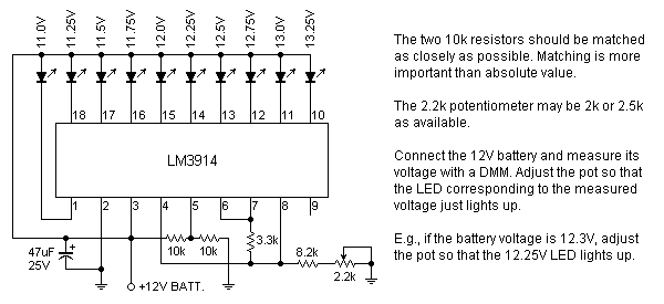
I'm thinking of basing it on an LM3914. I know you said earlier that it's not available in your local shops and I gave you two online sources in your country in post #6. But international giants like element14 (formerly Farnell) and RS tend to be rather expensive. If you can find them in one of the local shops, they are likely to be much cheaper. The LM3914 is a popular IC and it's likely that some local shops have it. I suggest you ask again.

Anyway, if you cannot find the LM3914, the battery monitor can also be made with quad opamps and comparators like the LM324 or LM339.

---------- Post added at 21:34 ---------- Previous post was at 21:09 ----------

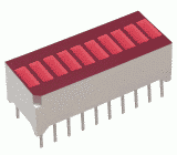
By the way, you may also be interested in a bar graph LED module like this. They look nice and are not expensive. They come in common-anode and common-cathode versions. We need the common-anode version for this project.

85_1325693027.png

Sir,

I have checked the LM3914 and unfortunately its not available but the LM324 and LM339 are both available sir.
 
Last edited:

Here's the battery monitoring circuit. The scale is 11V to 13.25V with a resolution of 0.25V. It can be used and adjusted with the battery alone without hooking it up to the UPS unit.

98_1325750835.png


BradtheRad brought up a valid point earlier in post #7 regarding current drain on the battery by the monitor circuit when it's not being charged by the UPS circuit. I've reduced the LED current to about 5mA. With the current drawn by the IC itself, the total drain on the battery is about 10mA.

When everything is connected together, the two regulator ICs also draw standby currents of about 5mA each even if the loads are disconnected. Thus, the total idle current is about 20mA. This drains 10% of the battery's capacity in 24 hours, but only if mains power is off. If it's kept connected to the mains, the idle current is supplied by the mains and does not drain the battery.

Therefore, if the whole circuit is to be disconnected from the mains for extended periods, it will be best to disconnect the battery from the rest of the circuit. A switch between the battery and the rest of the circuit will be a convenient way to do that.

sir, ive found the LM3914 but it has an N, LM3914N, ive already bought it sir. i have a question,

how will i connect the battery monitoring with the circuit and battery since im confused with regards on above explanation.

about the battery monitoring circuit, what are the resistors wattage.

and the UPS circuit, is it ok to increased the 22 Ohms 2 Watts to 22 Ohms 5 watts? and is it a wirewound? ive already bought the components UPS circuit and bought a 22 Ohms 5 W wirewound resistors
 
Last edited:

Nice to know that you managed to get an LM3914. I had already designed a circuit using two LM339 comparator ICs, but the LM3914 design is more compact. Don't worry about the N suffix. Popular ICs are often made in many different packages, temperature range, etc. The N simply denotes that particular type of plastic package. Such suffixes are often omitted in schematics and discussions.

how will i connect the battery monitoring with the circuit and battery since im confused with regards on above explanation.
The battery is connected to the UPS as in the schematic. The monitoring circuit is connected to the battery as in the schematic. That is, the battery is connected to both the UPS and the monitor circuit at the same time. The "+12V BATT" terminal at the bottom of the schematic goes to the battery and serves as both the power supply and the voltage sensing point. This is shown in the diagram below which shows parts of the UPS and the monitor circuits -

28_1325935729.png


about the battery monitoring circuit, what are the resistors wattage.

and the UPS circuit, is it ok to increased the 22 Ohms 2 Watts to 22 Ohms 5 watts? and is it a wirewound? ive already bought the components UPS circuit and bought a 22 Ohms 5 W wirewound resistors
There is no 2.2 ohm resistor in the UPS circuit. It's 22 ohms. Yes, it's OK to use a 5W resistor, and wirewound is fine too. All other resistors are 1/4W. It's OK to use higher wattages, the only difference being that they will be bigger and more expensive.

If you're still not clear about something, just ask again.
 
Sir, question.

i didn't get the battery switch explanation.

My understanding about this is, if the whole system don't have any power at all and unused for several days, the battery switch will disconnect the battery itself from the circuit? but why the battery must be disconnected?

like, if the battery can supply the system full of charge, lets say 4 hours, after 4 hours, the battery can't supply the system and the switch takes over to disconnect the battery from the circuit?

and i dont understand why the switch will prevent unneccesarry drain on the battery?

maybe i don't know yet the tolerance of the battery if what amount of V will it be low voltage and full of charge. im not quite sure about my understanding sir, please do really correct me if im wrong. thanks in all the way
 

The switch is not automatic. I put it there only as a convenient way of disconnecting the battery from the rest of the circuit. It's not essential.

When the whole thing is disconnected from the mains, the battery does not receive any charge. But the monitoring circuit and the the two 780x regulators are always drawing a small amount of current from the battery (about 20mA). Therefore, it's desireable to disconnect the battery if it's to remain unused and unplugged from the mains. You turn off the switch or simply disconnect the battery terminals from the rest of the circuit.

An automatic switch can be made to disconnect the battery if the voltage falls below a certain level, but that will add more complexity.
 
Sir, how can you tell that the battery can/cant supply the system? according on the battery monitoring, the lowest led which has a 11.0 V, with in this state. can the battery supply the system? if lower than 11.0 V we must disconnect the battery from the system?
 

One section of your project needs 9V which is supplied through the 7809 regulator. A 78xx regulator needs an input voltage at least about 2V higher than the output, which is 11V for the 7809. (The minimum 2V difference between input and output is called the drop-out voltage of the regulator). If the battery voltage drops below 11V, the output may drop below 9V too. But the drop-out voltage is not an exact figure and depends to some extent on the load current.

Your project may still work somewhat below 9V. It depends on the design and the parts used. The 5V section should still work even when the battery voltage has dropped to about 7V.

However, it's not good for the battery to keep using it after its voltage has dropped to about 11V. Over-discharging as well as overcharging can shorten battery life. If the UPS + battery is connected to the mains, the UPS (not the battery) will power the load and also charge the battery at the same time. It's when you use the battery to power the load in the absence of mains power that you have to watch the state of the battery. Don't let the voltage drop below 11V unless it's an emergency.

If there's no mains power and you supply your project using the battery, stop when the battery has dropped below 11V and disconnect it until you have mains power again.
 
Thanks for a detailed explanation sir, now i truly understand the UPS unit that we are working on.
Sir, since i have all the components of the UPS circuit, when i completely done mounting them on a PCB, and if we are testing the system with different modules/ loads, is it ok to connect the battery to the circuit while the mains are on? i mean, that would not overcharge it? cause i was planning during our defense proposal, since the requirement back up time for the UPS system is 30-45 minutes, i am planning to off the mains, let the battery supply the system until the 30-45 minutes time reach, so i can prove to the panelists that one of there requirements had been satisfied by the UPS system, since the circuit can last 2-3 hours right?
 

Yes, it's OK to have the battery connected when the mains is on. The whole idea of a UPS is to charge the battery when there's mains power, and use battery power when there's no mains.

Since there's no automatic charging control, the battery may get overcharged if you keep it connected to the mains for several days. But the charging rate is not high and damage to the battery will be very slight and very slow. It will be best not to keep it connected to the mains for more than a few days at most.
 
Abiso ng Redirect

sir,

i have a question regarding LM323, how can we mount it with heatsink? i mean which is the pin in and pin out. since ive bought a LM323K. it has a plastic same size and look with LM323K. should i also mount it between the LM323K and heatsink? thanks sir
 

Look at the bottom (pin side) of the IC and the drawing below. Notice that the two pins are not quite in the centre length-wise. In the drawing, the pins are slightly to the left of the centre line. It's made this way so that the pins can be identified easily.

47_1326130846.png


This type of case is called a TO-3 and is one of many case types in the TO series where TO = transistor outline. The TO series were standardized since the early days of transistor technology. Other examples are TO-92 (BC547, 2N3904, 2SC945), TO-220 (7805, 2N6292, IRF540).

Regarding the "plastic", if it's transparent, it's a mica sheet. If it's not transparent, it's a synthetic material. Those materials (mica or synthetic) are electrical insulators but good conductors of heat. A material with those two properties is quite rare because most electrical insulators are also bad conductors and good conductors of heat are usually good conductors of electricity.

It's meant for electrically insulating the regulator (or a transistor) from the heatsink while providing good heat conduction. But you don't have to use it in this UPS design because the regulator case is also the ground terminal. Connection to the case is made by screwing on a solder tag washer like this:
26_1326130885.png
 
Sir,

Regarding the plastic, its transparent sir. But, since youve said its not necessary for the circuit, i wont used it sir. Regarding the solder tag, i don't have that and never seen it.

Abiso ng Redirect

above link is a solder tag right? but never seen it in real.

queston sir, since the LM323K, its casing is a ground, mounting it on the heatsink make the heatsink ground too? i mean, the heatsink will be mounted on common ground on the circuit? or let it be hang?im kinda confuse mounting LM323K on the heatsink if there's an effect on it and mounting the heatsink itself on the PCB.

Abiso ng Redirect

sir, just to add it up how solder tag mounted.

---------- Post added at 03:30 ---------- Previous post was at 03:20 ----------

https://www.lencoheaven.net/forum/index.php?topic=1096.0

sir, another topic regarding solder tag. so the solder tag is screwed up together with a ball and knot on the casing of LM323K with the heatsink? but what if we dont have any casing at all sir, i mean the circuit is open and no casing at all. is it really necessary to ground the casing of LM323K connected to the earth ground? please correct me if im wrong
 
Last edited:

Sir,

Regarding the plastic, its transparent sir. But, since youve said its not necessary for the circuit, i wont used it sir. Regarding the solder tag, i don't have that and never seen it.

Abiso ng Redirect

above link is a solder tag right? but never seen it in real.
Yes, that's a solder tag. It's also called a lug.

queston sir, since the LM323K, its casing is a ground, mounting it on the heatsink make the heatsink ground too? i mean, the heatsink will be mounted on common ground on the circuit? or let it be hang?im kinda confuse mounting LM323K on the heatsink if there's an effect on it and mounting the heatsink itself on the PCB.

Abiso ng Redirect

sir, just to add it up how solder tag mounted.
A solder tag is simply a way of making an electrical connection when it's not convenient to solder it directly.

[/COLOR]https://www.lencoheaven.net/forum/index.php?topic=1096.0

sir, another topic regarding solder tag. so the solder tag is screwed up together with a ball and knot on the casing of LM323K with the heatsink? but what if we dont have any casing at all sir, i mean the circuit is open and no casing at all. is it really necessary to ground the casing of LM323K connected to the earth ground? please correct me if im wrong
I';m not sure what you mean by "what if we dont have any casing at all". TO-3 ICs and transistors use the case (metal body) as one of the terminals. With a BJT, it's the collector. With a MOSFET, it's the drain. With an LM323K, it's the ground terminal. So the appropriate connection must be made to the case. With an LM323, the ground terminal must be connected to circuit ground.

Except for certain situations where the heatsink is very small and it's more convenient to leave it floating, it's always a good idea to connect it to ground.
 
Redirect Notice

i think ive got it sir, regarding the above link is a TO3 regulator, the solder tag mounted on the casing of LM323k which equals to ground, but what im not really sure if the wire connected on the solder tag and LM323k Casing, will it be mounted on the Circuit's Ground?
 

The TO-3 devices in your link are transistors, not regulators, but the method of connecting the case is the same. Frankly, I don't know what you still find unclear about making a connection to the case. Think of the metal case as one kind of pin. Since it's not convenient to solder a wire directly to the case, we use a screw-on connection. That's all, really.

In your link, the case is the collector of a PNP BJT, so the wire goes to where the collector is to be connected. With an LM323K, the case is the ground pin, just like the middle pin on a 7805. So the wire from the solder tag screwed on to the case goes to the ground line on the PCB. The wire should not be longer than necessary.

By the way, look at the UPS schematic and you will see two 0.1uF capacitors, one each from the outputs of the two regulators to ground. To avoid possible instability, those capacitors should be as close to the regulators as possible.
 
Maybe this will make things clearer: With an LM323K or a 78xx regulator, the ground is not just a shield or a cover. It is an essential part of the internal circuit. Therefore it must be properly connected to the rest of the external circuit.

On the other hand, the case of an LM338K or LM317 is NOT ground. The case serves as the output pin. These adjustable regulators do not have a ground terminal. They are floating devices and their only connection to circuit ground is through the voltage setting resistor. Therefore, if an LM338 or LM317 is mounted on a grounded heatsink, it must be insulated from the heatsink.
 
Yes sir, it really makes things clear out now, how LM323K will be mounted,its ground or casing is also part of the circuit will it will be connected to it. I was thinking another thing and was wrong.

By the way sir, about the battery monitoring, if i don't have bar graph LED, can i used LED only? on one store bar graph LED is not available but hoping on the other shop it will. thanks sir
 

Yes, of course you can use individual LEDs as indicators. The bar graph module is just one option and I mentioned it because it looks nice, but you don't have to use it.
 
Sir,

im charging my battery right now, one of the seller on electronics shop that the battery is not charge, i was testing your circuit without the mains, and expected that the battery will back up the circuit, but did not, so i was asked to charge the battery 8-9 hours. tomorrow sir ill going to test the outputs through VOM since i dont have any VOM here sir, ill borrow some from my classmate.
 

If you're going to get involved in electronics, one of the first things you should have is a multimeter. In the old days, not everyone could afford to have a digital multimeter (DMM) and top grade DMMs are still quite costly even today. But there are many cheap Chinese products everywhere now and there's a wide range to choose from. I suggest you get one ASAP.

Also check and double-check your construction. It's very easy to get something wrong even for an experienced person.
 
Status
Not open for further replies.

Part and Inventory Search

Welcome to EDABoard.com

Sponsor

Back
Top