Continue to Site

Welcome to EDAboard.com

Welcome to our site! EDAboard.com is an international Electronics Discussion Forum focused on EDA software, circuits, schematics, books, theory, papers, asic, pld, 8051, DSP, Network, RF, Analog Design, PCB, Service Manuals... and a whole lot more! To participate you need to register. Registration is free. Click here to register now.

Optical Switch assistance

Status
Not open for further replies.

Alys Bach

Newbie level 6
Joined
Dec 29, 2011
Messages
11
Helped
0
Reputation
0
Reaction score
0
Trophy points
1,281
Activity points
1,376
Hi All

I’m an electrical engineer by training but haven’t been involved much with electrical work for many years, hence a lot of catching up to do. I haven’t dealt with electronics since I was an apprentice in the 1970’s but have always had an interest in the subject and still have a good understanding (although not up to date)

I have a problem to solve that you guys may be able to help with.

I want to make a rudder position indicator for my boat. All I need to know is when the tiller arm is in one specific position (mid-ships). The wiring isn’t a problem and I think I know an easy way of doing it that I can make waterproof.

What I’d like to do is make a photo switch using an IR LED and an appropriate phototransistor/diode.

Basically the tiller arm is in a very dark location, what I was thinking of doing was attaching a reflector to the tiller arm so that when the reflector is under the LED and Photo device a relay is operated, this would preferably be an electronic relay which would allow me to pot up the unit in resin to keep out the moisture when installed.

The electronic relay will then be used to feed a lager relay coil to allow me to connect up two flashing lights and two sounders which are a considerable distance from the tiller, hence the need for an additional relay to allow for the voltage drop.

Basically has anyone built an optical switch that would be capable of performing this task and what components did you use?

I’ve looked at loads of sites but keep coming up with different answers

Any help would be appreciated and thanks in anticipation

Kind regards

Paul
 

Yes I have done something similar. The device I used was a module with transmitter and reciever led pair built together. A reflective surface was used to bounce off. You might consider using a hall effect and a magnet also. This too would require no power on the tiller. Just a magnet mounted on it. As the magnetic field comes close enough to the hall effect device it will trigger. If you want to stay with the opto then maybe something like a position detector pair used to detect paper position in printers would work. The problem is the working distance. Just thoughs.

dfullmer
 

Many thanks for your reply

Please excuse my ignorance, what is the hall effect? Does the magnet need to be moving for it to work?

I thought of using a product from Honeywell’s HOA 1387 range but couldn’t figure out the circuit components to go with it.(especially for 12v)

The relay I came across which looked suitable was from Texas Instruments TS12A4514, but I may be able to drive a conventional relay directly by using an op amp

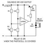
I was thinking of using National semi conductors LM393 as the amplifier using the circuit below, but would need to modify it to get it working


Am I progressing in the right direction?

KR

Paul relay circuit.jpg
 

No worries. Hall effect is a simple device that can be activated by a magnetic field. The magnet does not need to be moving, just present. The circuit you uploaded seems fine for the optical track.
 

Hi

how do I go about calculating the value for R1?

K R

Paul
 

That will depend on the photocell you use and how much light will create how much current draw through R1. I assume it is a photo conductor. So when light hits the cell it conducts. The amount of current it conducts will depend on how much light hits it. Many of these cells are actually rated in terms of current in amps per milliwatts per sq area. The cell will need to be able to pull the voltage down below 6V which is on the other leg of the comparator. So if the cell can only pull a milliamp then R1 would be 12K.
 

Hi

I'm looking at the data sheet on https://www.farnell.com/datasheets/97217.pdf

from what I can see the output at a gap of 0.04" is 1mA is this correct or is dependant on the quality of the reflective material? If this is the case the if I use a 0-12K pot and say an 8K resistor I should be able to fine tune it.

KR

Paul
 

Yes I think that is reasonable. However if I were you I would make the 8K, 50K instead. Some of the cells look like they are a min collector current of 0.2 ma. Wouldn't hurt anyway.
 

Many thanks for your assistance, I'll go with the 50K and work my way down in 10K steps till I get it. I think there will be a bit of trial and error with this.

Will let you know how I get on

KR

Paul
 

Speaking of magnetic action...

If the distance involved is not too large, you can use a magnet and reed switch.

Mount the magnet on the moving part, and put the reed switch close by.

What if you need a larger range of movement for the 'on' state? Use a row of magnets, or a row of switches in parallel.
 

Thanks Brad,

I had considered this option but there are all sorts of metals around there and an electric motor for the auto pilot so passed on it.

It would have been a lot simpler as that's the type of thing I'm used too.

I think I've got the circuit sorted out now but would not want to bet my house on it.

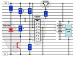
I've attached it, any comments would be appreciated. It has been laid out to be soldered to a board so looks a little oddSwitch circuit.jpg
 

Hi All

one quick question, is there any free software available for designing PCB boards that are easy to use? I looked a couple but they seemed like you needed to be above my level of expertise to use.

KR

Paul
 

Your schematic looks okay. Your use of the 339 appears correct.

The datasheet for the 339 advises to tie any unused input pins to ground. This stops the possibility of internal oscillations that waste power or cause improper IC performance.

The comparator presents either high impedance at the output pin, or it presents an internal path to ground at the output pin. You are connecting it through a 1k resistor to the bias of your PNP transistor. It will bias the transistor properly when comparator output is low. And it may be all right when the ouput is at high-impedance. However if the PNP acts in an unexpected manner, you may want to install a pullup resistor (5k to 50k) going from 12V supply to the bias leg of the PNP.
 
Many thanks Brad for having a look at this for me. The more I'm doing electronics wise of late the more it's coming back to me from my apprenticeship 40 years ago. I've retired now and seem to have time for thing that I never did before, hence my return to looking at electronics after all these years.

I might as well put the pull up resistor in to begin with as it can only do good things looking at it, I think a higher end value should work better, say about 30k, I can't remember how to work it out properly, is there a formula?

Do I need to tie both the +ve and -ve input pins to ground? I couldn't find it in the data sheet, its probably there but I missed it.

KR

Paul
 

30k should work for the pullup resistor. It's adequate to drain away rogue charge at the transistor bias. And sufficiently high that it won't interfere with pull-down signal from the comparator.

As for +ve and -ve, I'm not sure what pins these refer to, but going to the databook diagram... The unused inputs on the 339 are pins 4, 5, 8, 9, 10, 11. These should be tied to ground according to the databook.

You do not need to connect anything to unused output pins 2, 13, 14.
 

Hi Brad,

Many thanks for your reply, did you have a look at my revised drawing? I've left the track unbroken under the IC in certain places to short out the unused inputs (both +ve and -ve) to cut down on the amount of soldering to get them all to ground. Have I put the resistor in the circuit correctly, I think I have.

I was recommended to have a look at a programme today that checks out circuits to ensure that they will work. It was called YENKA have you ever used it or do you know anyone that uses it before i down load it?

KR

Paul
 

I guess you'll have to make a new post showing your updated schematic.

Whichever pins are +ve and -ve, please label them clearly.

Yenka has been around a few years. Saw the website once but I forget whether I tried it. Is that the one that costs $440 as shareware? For that price they ought to let you try it for a while for free.

There are lower cost electronic circuit simulators. Some free. Posters here refer to various programs. Such as Spice, LTSpice, etc.
 

Hi Brad

Happy New Year to you.

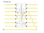
I'm happy with the +ve and -ve inputs groundings on the drawing as they are opposite each other which makes it easy. Attached is the drawing of how i cut the track

I have noticed something that I have done wrongly though. I have ordered the wrong part. I've ordered the HOA 1397 032 by accident, this is a Darlington pair version, will my existing circuit still work? (link to data sheet)

KR

Paul
 

Hi Brad

Happy New Year to you.

I'm happy with the +ve and -ve inputs groundings on the drawing as they are opposite each other which makes it easy. Attached is the drawing of how i cut the track

Chip.jpg

I have noticed something that I have done wrongly though. I have ordered the wrong part. I've ordered the HOA 1397 032 by accident, this is a Darlington pair version, will my existing circuit still work? (link to data sheet)

KR

Paul
 

Status
Not open for further replies.

Similar threads

Part and Inventory Search

Welcome to EDABoard.com

Sponsor

Back
Top