eclisia
Newbie level 3
Dear All,
By advance, thanks a lot to all contributors of this forum !
In the past, the advices of the various topics were very helpful for me.
I have a newbie question.
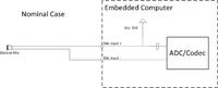
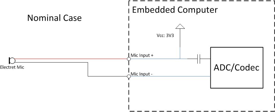
For a personal project, I want to connect electret microphone to input microphone.
The Input microphone has the specifications of electret input (as input of PC) : with bias voltage (3V3), impedance, etc..
Electret microphone, that I want to use, is compliant with this input. No problem.
(see image below)
Indeed, the question is the following:
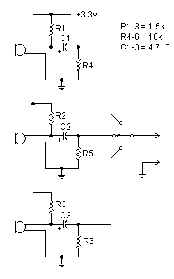
==>How connect 3 electret microphones to this input, using only Switch Relay?
In fact, the constraints of my personal project are:
• use only 2 relays/switch (SPDT) or 1 commutation selector (3 positions),
• use 2 wiring configuration for electret (bias and signal + on the same wire)
I have thought about two solutions:
Notice :
I’m aware that with integrated circuit, better solutions exist.
Or with mixer technologie, etc…
But, it doesn’t match with the constraints of my project.
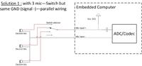
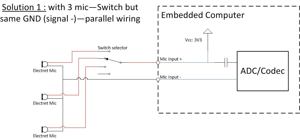
First solution :
Use the same grounding wires, and use the commutation selector to select the way.
(see image below).
Is there any risk of ground noise?
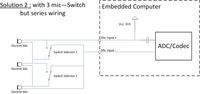
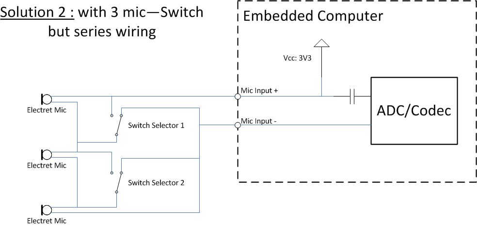
Second solution:
Use of 2 SPDT switch. The electret microphones are wired in series configuration.
Each switch permits to enable short circuit at microphone.
(see image below)
Do you have any advices? Criticizes or remarks ?
In all case, thank a lot for your answers.
Best regards.
By advance, thanks a lot to all contributors of this forum !
In the past, the advices of the various topics were very helpful for me.
I have a newbie question.
For a personal project, I want to connect electret microphone to input microphone.
The Input microphone has the specifications of electret input (as input of PC) : with bias voltage (3V3), impedance, etc..
Electret microphone, that I want to use, is compliant with this input. No problem.
(see image below)
Indeed, the question is the following:
==>How connect 3 electret microphones to this input, using only Switch Relay?
In fact, the constraints of my personal project are:
• use only 2 relays/switch (SPDT) or 1 commutation selector (3 positions),
• use 2 wiring configuration for electret (bias and signal + on the same wire)
I have thought about two solutions:
Notice :
I’m aware that with integrated circuit, better solutions exist.
Or with mixer technologie, etc…
But, it doesn’t match with the constraints of my project.
First solution :
Use the same grounding wires, and use the commutation selector to select the way.
(see image below).
Is there any risk of ground noise?
Second solution:
Use of 2 SPDT switch. The electret microphones are wired in series configuration.
Each switch permits to enable short circuit at microphone.
(see image below)
Do you have any advices? Criticizes or remarks ?
In all case, thank a lot for your answers.
Best regards.