Continue to Site

Welcome to EDAboard.com

Welcome to our site! EDAboard.com is an international Electronics Discussion Forum focused on EDA software, circuits, schematics, books, theory, papers, asic, pld, 8051, DSP, Network, RF, Analog Design, PCB, Service Manuals... and a whole lot more! To participate you need to register. Registration is free. Click here to register now.

Differential amp: capacitance at input

Status
Not open for further replies.

seyyah

Advanced Member level 2
Joined
Oct 7, 2001
Messages
646
Helped
8
Reputation
16
Reaction score
8
Trophy points
1,298
Activity points
6,233
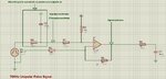
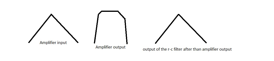
I have a circuit with a ths421 opamp. There is a pulsed signal at the input and after that there is an RC circuit. Output of the RC circuit is triangular signal and is input to the differential amplifier. I think i should see the same waveform at the output of the amplifier but i don't see exactly. If i see, it a distorted pulse. Sometimes i don't see anything. Differential amplifier's resistors affect the result. The amplifier is fed from 5V single supply and input of the amplifier is 2.5V to 3.5V triangular shape signal. What may be the reason of this. Why cannot it transfer or amplify the signal. What should we care in this kind of circumstances. Thanks.
 

Attachments

  • diffamp.jpg
    diffamp.jpg
    308.5 KB · Views: 97

The reason for the triangular wave form is that when your pulse appears, C2 starts to charge, then if the pulse disappears, discharges. because the charge and discharge resistors are unequal in value, the voltage across them appears to be triangular. if things are coming and going then you must have a loose connection or a bad componet in your circuit.
Frank
 

Your opamp might need a resistor from output to ground.
No change. Also i want to mention that the output goes to a comparator.

---------- Post added at 11:59 ---------- Previous post was at 11:57 ----------

I'm not concerning about triangular waveform. But i want to see it at the output; exactly the same waveform. But sometimes it is distorted pulse and sometimes there is none. If there is a distorted pulse the last R-C section corrects it and a similar waveform is obtained with the input signal.

The reason for the triangular wave form is that when your pulse appears, C2 starts to charge, then if the pulse disappears, discharges. because the charge and discharge resistors are unequal in value, the voltage across them appears to be triangular. if things are coming and going then you must have a loose connection or a bad componet in your circuit.
Frank
 

What's a strange schematic )) Where did you get it?
You dividing signal by 2 and then multiplying by 2.
Attach, please, whole project. I will try to simulate it.
 

Some problems with your post
- You didn't show (or at least sketch) a waveform
- The schematic is incomplete
- THS421 isn't a known part
 

I agree with Easyrider83. Why did you divide the triangular signal by 2 then you amplify it by 2 ? the circuit do like multiplying the triangular signal by (2/2) which mean 1.

Please try removing the non-inverting amplifier circuit because there is no need for it. Or try amplifying the triangular wave by removing the voltage divider (placed before the Op Amp non-inverting input). This will amplify your signal by 2.
 

Why did you divide the triangular signal by 2 then you amplify it by 2 ?
As seyyah mentioned it's just a standard differential amplifier circuit. I don't know, if it serves a purpose here, but it shouldn't be a reason for getting distorted signals.

You should consider however, that by placing an additional 47k resistor, the differential amplifier looses ir's common mode rejection.

Before commenting the original problem, I'm waiting for additional information.
 

What's a strange schematic )) Where did you get it?
You dividing signal by 2 and then multiplying by 2.
Attach, please, whole project. I will try to simulate it.

That is a standard differential amplifier with a gain of 1, there is nothing strange about it.
 

The differential amplifier is on purpose, that is not the question here. I'm sorry the part was ths4221. I think the problem is the values. The square waveform generator does represent another system actually and it produces some kind of noisy signal and the r-c filter after that also outputs a noisy triangular waveform. But not much noise. But the signal's frequency is not stable. It's changing rapidly around a center frequency. I've made a crude sketch. The ouput of the amplifier seems that it's cropped a bit but sould not be because the signal's peak value is 3.5V or so and the amplifier works with 5V single supply. The input and output triangular waveforms are almost same with a small phase and amplitude difference.


Aha!The THS4221 is a rail-to-rail OUTPUT amplifier. It is NOT rail-to-rail input. Your input can't go any closer than about 1V from either rail; in other words, your input is constrained to be between 1 and 4 volts with a 5 volt supply.
 

The most serious performance restriction will be imposed by the 5V single supply operation. Typical common mode range is 1 to 4 V according to the data sheet. This means, that your circuit won't reproduce analog input voltages below about 2V.

There are most likely additional problems of dynamic circuit behaviour, e.g related to input capacitance respectively relative high resistor values, but you didn't mention the timescale of the signals.

I fear however, that THS4221 won't achieve stable feedback operation with 100k resistors due to the pole formed by the amplifier input capacitance and the feedback network. Did you notice, that the datasheet suggests an optimal feedback resistor value of 1.3k for G=+2? Stability margin may be reached at about 10k.
 

As i've mentioned in my post the input signal varies between 2.5 to 3.5 and in some cases 1.75V to 3.5Volts. Frequency is about 100kHz. I've tried several resistors even the resistors that datasheet suggests but with low resistors i am losing signal more due to input capacitance i think, which is around hundred picofarads.
 

I've tried several resistors even the resistors that datasheet suggests but with low resistors i am losing signal more due to input capacitance i think, which is around hundred picofarads.

OP input capcitance is a few pF maximum, read the datasheet. As said, the high feedback network impendance brings up stability issues, in so far it's not an option to increase the dimensioning arbitrarily above the values suggested in the datasheet.

I simply can't imagine how low resistor values should cause signal losses due to input capcitances. It may be a problem, if the source impedance is too high. In this case, you either need to reduce the amplifier bandwidth or use input buffer(s) before the differential amplifier circuit.
 

Status
Not open for further replies.

Part and Inventory Search

Welcome to EDABoard.com

Sponsor

Back
Top