Continue to Site

Welcome to EDAboard.com

Welcome to our site! EDAboard.com is an international Electronics Discussion Forum focused on EDA software, circuits, schematics, books, theory, papers, asic, pld, 8051, DSP, Network, RF, Analog Design, PCB, Service Manuals... and a whole lot more! To participate you need to register. Registration is free. Click here to register now.

PIC controlling AC loads

Status
Not open for further replies.

romel_emperado

Advanced Member level 2
Joined
Jul 23, 2009
Messages
606
Helped
45
Reputation
132
Reaction score
65
Trophy points
1,318
Location
philippines
Activity points
6,061
hello.

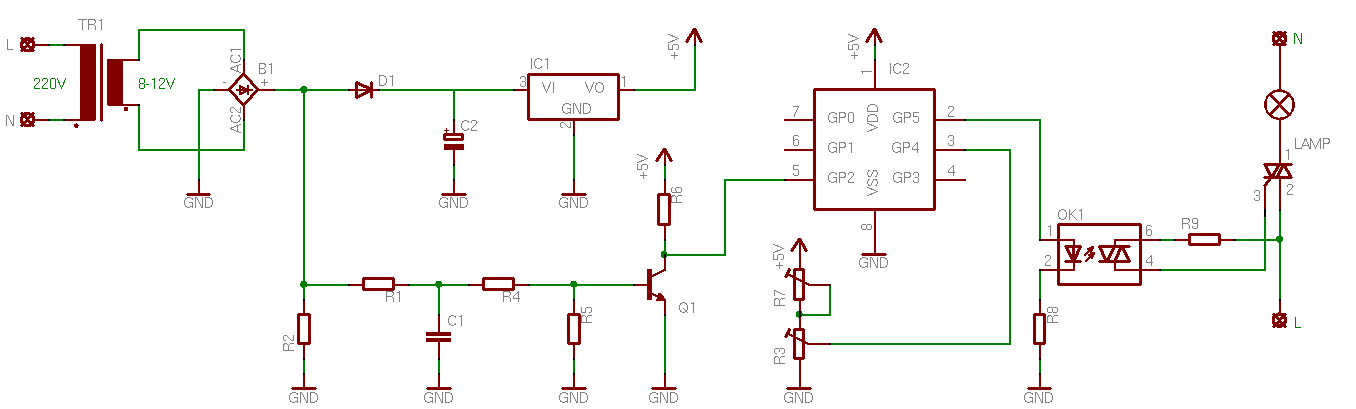
since I started learning pwm I want to use it in actual application.. Im thinking about controlling AC load such as 230vac light..

MOSFET for DC and cannot use in AC application right? Can you give me some hint how do I drive the triac via pwm? I cant actually get some of the explanation I am reading now...

---------- Post added at 01:48 ---------- Previous post was at 01:40 ----------

okay I foud this good document from microchip.. its worth reading./.
**broken link removed**

and it has also a pdf.
 

Re: PIC complete discussion for all

Here are a couple more appnotes and TRIAC based projects:


**broken link removed**

Triac regulation using PIC microcontroller

PIC DCV Controlled AC Light Dimmer

Another excellent project to demonstrate the use on PWM is RC Servo control. RC Servo Control is probably simpler to setup and the RC Servo itself is rather inexpensive. Another plus is the visual gratification of directly controlling the position of the servo is greater than dimming a light. :wink:

If you are interested in RC Servo control, let me know, I have quite a bit of info on the topic.

Ciao

---------- Post added at 01:46 ---------- Previous post was at 01:38 ----------

The project in this video is a bit advanced for you at the moment, however it does demonstrate the power of RC Servo motor control, two in fact.


Neat! Huh?

---------- Post added at 01:56 ---------- Previous post was at 01:46 ----------

Here is another example which is definitely doable. Notice the scope in the background display the current PWM waveform:


I had several contract projects which required controlling not these small RC servos, but very large servos, up to six at a time.

Ciao
 

Re: PIC complete discussion for all

wow very nice.. thanks so much.. I just mentioned this topic for my future reference..
 

Re: PIC complete discussion for all

You can pick a RC Servo at a hobby shop or via mail order for just a few dollars, most are 5v devices with three leads, 5v, GND and Control. They are controlled by varying the duty cycle of a PWM, but they can be fun.

The Color Tracking Camera is very neat.

---------- Post added at 02:51 ---------- Previous post was at 02:45 ----------

Did you have a chance to watch the video demonstrating PIC/TRIAC project under the "PIC DCV Controlled AC Light Dimmer," I posted above. It has some interesting variations of the standard light dimmer concept and the narrator's accent is great.
 
Re: PIC complete discussion for all

I got this site very detail about the dimmer circuit.. but the source code is written in assembly... ahaha lol I can make my own code as soon I understand the working of the circuitry.

PIC DCV Controlled AC Light Dimmer

base on this schematic there is a zero crossing detector circuit and it is driven to the GP2 of the PIC.. .

220px-Zero_crossing.svg.png

In alternating current, the zero-crossing is the instantaneous point at which there is no voltage present.


so one thing I dont understand.. the zero crossing detector circuit is connected after the diode so that is no longer AC then how would it detect the zero crosing point?

picdccontrolleddimmer_1272130733.png


---------- Post added at 04:51 ---------- Previous post was at 04:26 ----------

as per my understanding we can still detect zero crossing line even it is in DC because it is not well filtered yet..... not sure I just based that in the schematic provided.. hehe
 
Re: PIC complete discussion for all

I got this site very detail about the dimmer circuit.. but the source code is written in assembly... ahaha lol I can make my own code as soon I understand the working of the circuitry.

Sorry about that, sometimes I forget you haven't studied Assembly Language, better put that on your todo list!
I actually haven't had a chance to look at the code, but you should be able to figure out the register configurations for PWM and other peripherals.

so one thing I dont understand.. the zero crossing detector circuit is connected after the diode so that is no longer AC then how would it detect the zero crosing point?

Reference "PIC DCV Controlled AC Light Dimmer"
The transformer is used to provide both power to the circuit and to get the zero cross detection pulse. The 7805 is used to fix the supply to 5 Volts. There are 2 potentiometers connected in series. The first one (R7), is used to set the minimum luminosity (that needs the maximum trigger delay). The R3 is used to control the dimmer! This is actually the control potentiometer.

I hate messing high and low voltages. SAFETY FIRST! That's why i use the transformer for the zero cross detection (and not just some 4 MOhm resistors), and that's why i use the optocoupler. I use the MOC3021, for Greece has 220V mains. For 110/120 volts you may consider using the MOC3011. Check out the datasheet of the MOC series (find it in the Bill Of Materials section at the end of this article).

The zero cross detection point is still zero even with full-wave rectification. Which is then converted to a pulse or trigger and then feed into GP2.

Does this clarify the situation?

I'm playing with some new toys between replies, I just received a Bus Pirate.
 
Re: PIC complete discussion for all

Sorry about that, sometimes I forget you haven't studied Assembly Language, better put that on your todo list!
I actually haven't had a chance to look at the code, but you should be able to figure out the register configurations for PWM and other peripherals.

maybe The code isn't a problem I can make my own code if I know the process...


The zero cross detection point is still zero even with full-wave rectification.
ok,,, this is clear.

Which is then converted to a pulse or trigger and then feed into GP2
this is the problem I don't understand What is the process going on if the zero point is detected..
I understand this is the timing to control the pulse being feed to triac gate.. still unclear on this part.

---------- Post added at 06:55 ---------- Previous post was at 06:51 ----------

Bp-action-2ii.jpg

I feel this is a very good tool. .. hehe but I dont know this... hehe
 

Re: PIC complete discussion for all

this is the problem I don't understand What is the process going on if the zero point is detected..
I understand this is the timing to control the pulse being feed to triac gate.. still unclear on this part.


The NPN transistor forms an inverter, in other words as the transistor's base is driven very closely towards zero, the input signal in GP2 is high or '1'. Due to the fact the transistor base signal is a full wave rectification signal the zero point is of very short duration this produces a high pulse into GP2, which is sometimes referred to as a trigger.

The trigger then starts the PWM duty cycle and by varying the actual duty cycle the PIC controls the TRIACs ON state.

The RC network in front of the NPN transistor is for proper biasing of the base and a RC filter to remove unwanted harmonics.

Does this description help?

---------- Post added at 06:10 ---------- Previous post was at 06:06 ----------

Here is an interesting discussion on Zero-crossing detectors with PICs:

Zero-Crossing Detector

It mentions using a NPN inverter for a sharper pulse, post #11.
 
Re: PIC complete discussion for all

ah okay so this is the logic.. when the zero crossing is detected we activate our pwm or that's the time we drive out pwm to the gate of triac ?


and also I found this.. is this good enough?

**broken link removed**
 
Re: PIC complete discussion for all

ah okay so this is the logic.. when the zero crossing is detected we activate our pwm or that's the time we drive out pwm to the gate of triac ?

Correct, I have posted a couple of photos showing the resulting AC waveform along with the PWM controlling the TRIAC:

The the photos help you understand the TRIAC/PWM relationship, I'm not sure if they are using a zero-crossing detector in the second example, just remember the PWM in your project should start at the zero-crossing point.

and also I found this.. is this good enough?

PIC Writer Programmer - Microchip - WIDE.HK

Isn't this similar to what you are already have? I would recommend waiting for a used genuine Microchip ICD2. I have both ICD2 and ICD3s and still used both, I think the ICD2 is a little more rugged.
 
Last edited by a moderator:
Re: PIC complete discussion for all

Since the thread is up, let me just discuss this.
You can not use the PIC PWM to control an AC lamp using triac. You're supposed to be using phase angle control (or pulse skipping).
When you set PWM duty cycle at 20%, the output is high for the first 2ms and low for 8ms. But as soon as the output goes high, the MOC3021 fires the triac, which gets latched (on) until the next zero crossing.
Take any duty cycle and you'll see that the lamp will always light upto full brightness.
What you have to do is, if you need 20% brightness:
Half period is 10ms. So, your output needs to be on for 20% first half, then 20% second half. So, that means 80% off, this 80% is "cut" through phase control. Wait for 80% of the half-time, ie, 8ms and THEN send a high pulse to the MOC for about 100us and then turn the pulse low. Repeat this for the second half as well, and THEN you will get 20% brightness.

Phase fired controllers - Wikipedia, the free encyclopedia

15_1277448873.gif


Also take a look at these:
https://www.edaboard.com/threads/196141/#post822215
https://www.edaboard.com/threads/192839/#post808068

Hope this helps.
Tahmid.

---------- Post added at 23:49 ---------- Previous post was at 23:46 ----------

Plus, in the PIC, frequency is at 100s of Hz or in the kHz range. So, you can't use that. You have to sync the signal with the line frequency.
 
Re: PIC complete discussion for all

You can not use the PIC PWM to control an AC lamp using triac.

I'm afraid your statement is incorrect, I and countless others have successfully used a PIC, PWM and a TRIAC to control an AC load and there are numerous projects published online and in texts to support this fact.

While your option is a viable one, it is not the only option. A little more research on your part would be prudent before making such a statement.

Plus, in the PIC, frequency is at 100s of Hz or in the kHz range. So, you can't use that. You have to sync the signal with the line frequency.

A PWM frequency in the 100s, 10s or 1s of Hz are all doable, in fact fairly simple to generate. Utilizing the PIC's CCP/ECCP is an option not a requirement.

Hope this clears up any confusion,

BigDog
 
Hello guys..

thanks so much for the informative and useful replies...

I think all information here is enough and it's time to do my part... I will mark this thread as solved once I did..

thanks so much to alexan for reviving this very useful post and ckshivaram for reminding me about the rules..
 

When using triacs remember to include some kind of mains filter in your design. Triacs tend to generate massive noise in power network without proper filtering.
 
When using triacs remember to include some kind of mains filter in your design. Triacs tend to generate massive noise in power network without proper filtering.

are you referring also some isolation from the main line to my PIC?
 

Yes..PIC microcontrollers are vulnerable while working with AC designs. An optocoupler and a filter is recomended to keep EMI's at bay. While AVR's like the AT tiny 13 may also be implimented to work with AC where the microcontroller may bbe directly connected to AC live through a 2M2 resistor to sense the zerocrossing and the gate of the triac may be directly triggered by the micro eliminating the need of an opto isolator. I have used Attiny in my various designs and are prooved to work well even with capacitor based power supplies which provide compactness to the design.
Cheers
 
Re: PIC complete discussion for all

I'm afraid your statement is incorrect, I and countless others have successfully used a PIC, PWM and a TRIAC to control an AC load and there are numerous projects published online and in texts to support this fact.

While your option is a viable one, it is not the only option. A little more research on your part would be prudent before making such a statement.
I actually meant using the PWM in the kilohertz range generated from the CCP module. Guess I was being a little unclear. If you generate a PWM at line frequency, then, yes, of course it is possible.

A PWM frequency in the 100s, 10s or 1s of Hz are all doable, in fact fairly simple to generate. Utilizing the PIC's CCP/ECCP is an option not a requirement.

Hope this clears up any confusion,

BigDog

Of course, they are. I meant that using the PWM part of (E)CCP module, it would not be possible at high clock rates. Of course, you can use the compare module and Timer1 or other methods.

---------- Post added at 20:59 ---------- Previous post was at 20:56 ----------

Yes..PIC microcontrollers are vulnerable while working with AC designs. An optocoupler and a filter is recomended to keep EMI's at bay. While AVR's like the AT tiny 13 may also be implimented to work with AC where the microcontroller may bbe directly connected to AC live through a 2M2 resistor to sense the zerocrossing and the gate of the triac may be directly triggered by the micro eliminating the need of an opto isolator. I have used Attiny in my various designs and are prooved to work well even with capacitor based power supplies which provide compactness to the design.
Cheers

Yes, even I've worked with ATtiny's and have seen them to work well. However, I've also used PIC12F with capacitor-resistor-based transformless non-isolated power supplies and sensed mains zero-crossing with 1M resistor directly and fired triac (gate-sensitive ones) directly from PIC (I've used them mainly for phase angle control and pulse skipping modulation for IR based light and fan controllers) and they haven't failed yet. Maybe a question of choosing the right values and appropriate filtering and decoupling, I guess.

Hope this helps.
Tahmid.
 

I've also used PIC12F with capacitor-resistor-based transformless non-isolated power supplies and sensed mains zero-crossing with 1M resistor directly and fired triac (gate-sensitive ones) directly from PIC

are you referring something like this?


Capacitive-AC-DC.gif
 

Re: PIC complete discussion for all

Just a minor remark on the circuit shown on post #5.
The resistor R9 should be connected to pin 1 of the load triac.
That is all :)
Kerim
 

Status
Not open for further replies.

Part and Inventory Search

Welcome to EDABoard.com

Sponsor

Back
Top