roofingboom
Member level 4
Hi,
I am driving a transformer at 15khz with a square wave of +-200Volts. I wound a auxiliary coil on the transformer to measure what is applied to the primary. I want to be able to detect a DC component in the voltage that I apply to the primary and correct it in the next cycle by applying positive or negative voltage for a longer time to balance the flux.
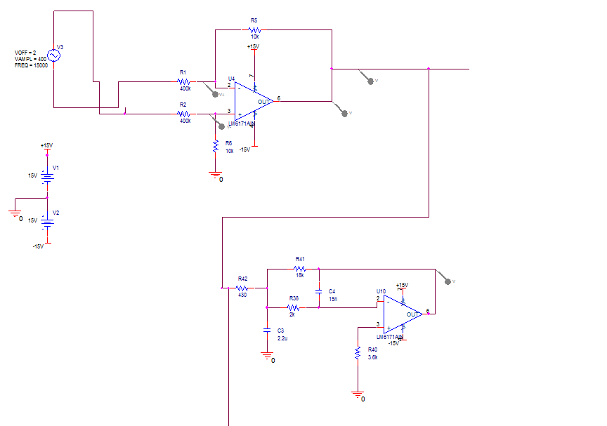
My first idea is posted here. The aux winding is 1:.5 and i used a diff op amp configuration to step down voltage to +-10v. Next stage is a MFB low pass active filter -3db set at 150Hz. The gain of MFB filter is inverse of the step down stage. I have attached the schematic. It does simulate well, but as of now not working in hardware. I an open to ideas to detected the flux in a transformer.
I would rather not sense both pri and sec currect to get magnetizing current because i would be treating the consequence instead of the cause.
I am driving a transformer at 15khz with a square wave of +-200Volts. I wound a auxiliary coil on the transformer to measure what is applied to the primary. I want to be able to detect a DC component in the voltage that I apply to the primary and correct it in the next cycle by applying positive or negative voltage for a longer time to balance the flux.
My first idea is posted here. The aux winding is 1:.5 and i used a diff op amp configuration to step down voltage to +-10v. Next stage is a MFB low pass active filter -3db set at 150Hz. The gain of MFB filter is inverse of the step down stage. I have attached the schematic. It does simulate well, but as of now not working in hardware. I an open to ideas to detected the flux in a transformer.
I would rather not sense both pri and sec currect to get magnetizing current because i would be treating the consequence instead of the cause.