powersys
Advanced Member level 1
Hi,
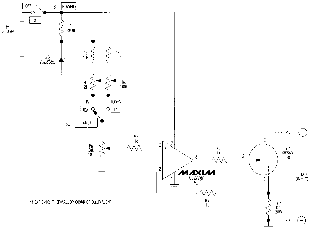
The electronic load shown in attached image is constructed using a power mosfet Q1 (IRF540). Let's say the opamp MAX480 is powered by a 9V battery, thus the maximum output voltage of the opamp should be no more than 9V. If the load current is 10A, the voltage drop across the R10 resistor is 0.1x10=1.0V. If it's a 12V load, then the Vds=12-(0.1x10)=11V. To conduct current, the Vgs must be larger then Vth of the power mosfet. In this case, the Vds>(Vgs-Vth) and the power mosfet should be operating in "saturation" region. However, the power mosfet is said to act like a voltage controlled variable resistor (in "linear" region) in several articles. Which one is correct?
Thanks.