Vermes
Advanced Member level 4
The main aim was the use of inertial sensors in humanoid robot control process to improve its motor skills. For this purpose, hardware and software platform was developed, including a robot Futaba RBT-1, robot controller, wireless communication module, the application run on a PC and simulation. Robot controller was based on the microcontroller with ARM7TDMI core and comes with complete inertial sensors system, RS485 bus to communicate with the robot's servo drives, wireless communication module 2.4 GHz and Bluetooth. The controller communicates with PC by a radio module connected to the USB port. Control application running on the PC was written in Microsoft Robotics Developer Studio, which is intended to create multi-threaded, distributed and scalable application used in robotics. The application uses the measurement results obtained by radio to the implementation of algorithms of walking and maintaining balance of the robot. Additionally, the application uses an artificial neural network to calculate the inverse kinematics of the robot legs. In order to visualize the robot's movements and to enable testing and development of algorithms without risk of damage, a simulation in Visual Simulation Environment was created. A 3D model robot in 3DS Max was used in the simulation.
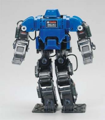
Futaba RBT-1
Humanoid robot Futaba RBT-1, shown in the figure below, was used in this work. This robot has 20 degrees of freedom – 6 for each leg, 3 for hands, one for the body and one for the head. The robot has a height of 255mm, 162mm in width (measured at the shoulders) and a weight of 900g. The main factor determining the choice of this model were digital servo drives dedicated to applications in robotics.
Wireless communication
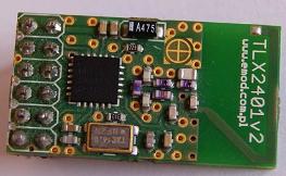
In order to provide wireless communication between the control application operating on a PC and the robot, a ready radio module TLX2401 was used with nRF2401 system Nordic Semiconductor Company, operating in unlicensed 2.4 GHz band. nRF2401 module independently manages the process of data sending and receiving. Microcontroller sends data by the SPI bus at any speed, the data is stored in the FIFO buffer before being sent. The module automatically generates packets to be sent and decodes the received packets.
Bluetooth module BTM-222, which has a virtual serial port profile SPP, was used for communication between the robot and the package Matlab/Simulink.
Servo drives
When choosing the mechanical structure of humanoid robot, the parameters of servo drives were the most important. Futaba RBT-1 robot has 20 digital servo drives. Although the digital servo RS301CR looks similar to the servo commonly used in modeling, it has many features that make it ideally suited to mobile robots.
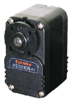
RS301CR is a small lightweight servo designed specifically to be used in robots. Low weight (28g) makes it suitable for control any structure with many degrees of freedom, such as the leg. It has a bidirectional RS485 bus for communicating with the control system. Communication takes place through specific commands sent from the master system, servo is a slave system. All the servos in the robot are connected to common RS485 bus. Each servo has its own unique ID number that is used in the transmission protocol. This type of connection method requires only two lines for control all drives. Communication takes place by means of specific commands set over the bus. Communication protocol allows you to control each individual or multiple drives at the same time with one command. A very important feature is ability to read the actual parameters of each drive. Current parameters are: position, speed, load, temperature, alarm flags. Servos have the opportunity to set the position and the time spent on it. This allows smooth movement without jerks. This is another important feature. The communication protocol allows you to change the internal settings of positioning each of the servos. Each servo is factory calibrated. The measurement position is done with 12-bit resolution.
Accelerometer and gyroscope
After analyzing the characteristics and parameters of different sensors, the choice was to use the complete inertial sensors system ADIS16362 from Analog Devices. Selected sensor has a triaxial accelerometer, triaxial gyroscope and a system of pre-processing the signals. The reason for choosing the sensor ADIS16362 was mainly the fact that each sensor is factory calibrated and has a compensation effect of temperature on the measurements of each internal sensors in the temperature range from -20to 70 degrees Celsius. Factory calibration is linearized sensor characteristics, elimination of the offset and the alignment of the sensors system axis. The sensor system has a serial SPI interface to communicate, read data, configuration. It has a miniature connector that is compatible with other series ADIS1635x sensors. The filter consists of two cascaded averaging filters with characteristics of Bartlett window.
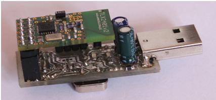
The project of radio module with USB interface
In order to provide wireless communication of the robot controller with the control application, communication module was developed. Radio modules TLX2401 were used as radio circuit. It was necessary to create a suitable intermediary system between the module and accessible TLX2401 computer interface, because a PC does not have a SPI interface. Due to the versatility, the USB was selected. Support of the radio system nRF2401 required the use of microcontroller with SPI bus. Since the microcontroller was designed to communicate with a computer, USB interface was also necessary. Due to the higher price of uC with an integrated USB, a separate converter USB<-> UART was applied, connected to the microcontroller by UART bus. The system used was Atmega88 Atmel.
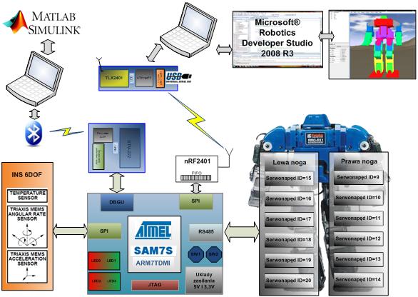
Schema of the Futaba RBT-1 robot control system
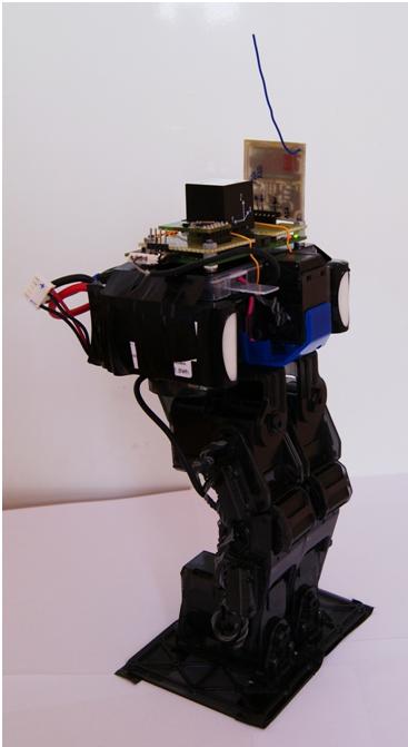
Assembled control unit with sensor and wireless communication modules:

Robot with assembled controller and Li-pol batteries on the sides of the body:
Programming part:
Determination of deflection on the basis of measurements of acceleration and angular velocity. Kalman filter is widely used in the INS systems. In robotics, this filter is used in Inertial Navigation Systems for filtration and fusion of measurements from the sensors that measure different parameters. In many commercial systems of INS, Kalman filter is used, and the obtained measurements are characterized by a high degree of accuracy. One of disadvantages is the need for frequent converting the measurements, and the algorithm is computationally quite complex. Due to the limited computing performance of microcontroller, requirements for the frequency of conversion were too high in relation to the possibilities. In order to implement the INS, an Efficient Orientation Filter for internal sensors was used.
Inverse kinematics of robot's legs was determined by means of artificial neural network in Matlab.
Control application
Robot controller reads data from its servos and the integrated inertial sensor. The controller sends the obtained data to a PC. Data is sent via radio with TLX2401 modules using ISM band (Industrial, Scientific, Medical) 2,4GHz, the use of which the license is not required. The computer receives data via a communication module equipped with TLX2401 module, connected to its USB port. Additionally, the robot uses Bluetooth to transmit the measurements of accelerometers and information about the excursion of the robot to Matlab to illustrate them on the chart. A program written in Microsoft Robotic Developer Studio (MRDS), running on the PC, implements the algorithm of walking and maintaining balance of the robot. It calculates (based on data received by the position of each servo and robotic excursion), the new values of bending angles of each joint. The calculated data are sent wirelessly back to the robot. The program also uses the simulation environment, part of MRDS, to visualize and simulate the behaviour of the robot. This makes possible to develop and test control algorithms without connected robot.
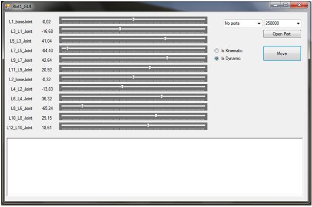
A simple graphical interface was created in order to allow the user to control the robot and the simulation.
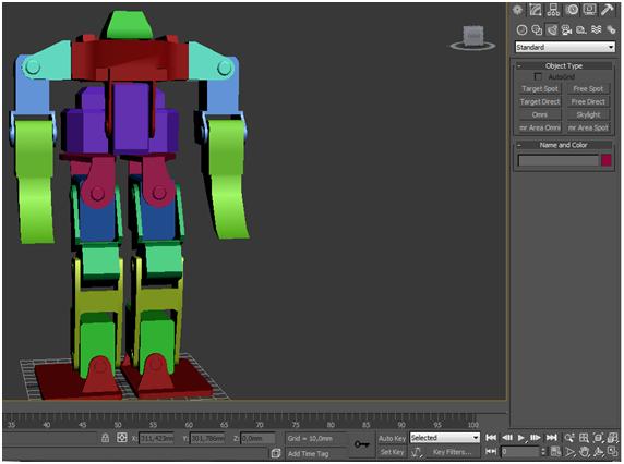
Simulation
In order to simulate the robot in a simulation environment Microsoft Robotics Developer Studio VSE, its three-dimensional model in 3DS Max was created. Then the model was moved to the VSE simulation environment. The model consists of 21 parts, each of them has a different colour to enhance the visibility. Each of these parts was transferred to the simulation environment as a separate obj. file. The robot's body was selected as a base object. Each part that connects to the base object is associated with it a parent-child relationship and itself becomes a parent for the next parts that are connected with it. In this way, all components of the robot form a hierarchy on top of which there is an object representing the body. The elements are connected together by joints with one degree of freedom.
Description of the control application
Application allows to operate in two modes:
- simulation mode – the application is in this mode when there is no physical connection to the real robot. In this mode, the controlled object is the robot model placed in the simulation
- control mode – application communicates with the robot through the serial port, receives status information and sends the control commands. In this mode the simulation is used as a visualization of the actual state of the robot.
Link to original thread (useful attachment) – Sterowanie robotem humanoidalnym Futaba RBT-1