Continue to Site

Welcome to EDAboard.com

Welcome to our site! EDAboard.com is an international Electronics Discussion Forum focused on EDA software, circuits, schematics, books, theory, papers, asic, pld, 8051, DSP, Network, RF, Analog Design, PCB, Service Manuals... and a whole lot more! To participate you need to register. Registration is free. Click here to register now.

Noise generation and role of capacitor in circuit

Status
Not open for further replies.

scorrpeio

Full Member level 5
Joined
Dec 26, 2006
Messages
286
Helped
10
Reputation
20
Reaction score
9
Trophy points
1,298
Activity points
3,496
Hello,

Few basic questions...

1. Noise is created because of different reasons. I read that while AC is rectified to DC using rectifier, a noise is generated. But nowhere it is mentioned How? (It was an article proving battery is the clean source of power than rectifier.)
2. Can anyone throw a light on how noise is generated in rectification?
3. Basically, what exactly is noise? Is it just an unwanted voltage at unwanted time and place?
4. When we say, capacitor filters noise, what does it exactly do? I know that capacitor absorbs noise. But, what does exactly happen during that process?
5. Normally, noise absorbing ceramic capacitors dont have polarity. How do they exactly function?
6. We often connect noise absorbing capacitor in parallel. Why not in series? (This question might be ridiculous for those who are experts, but I am asked this by my junior and I could not answer it. :cry: )
 
Last edited:

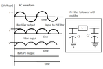
Hi Just get the look at the picture I am attaching here what capacitor charges up to max voltage and dischages when there is voltage dip......that the way it filters out the halfcycle DC to to mearly DC.....Kindly please note that battary will always give you constant voltage figure_waveform.png
 
Last edited:
Noise in rectifiers is due to non-linear behavior of silicon, loss in transformers and wiring loss..

Yes, noise is unwanted voltage in an unwanted place at unwanted time :)

Capacitor gets charged fast during the rise edge of a time varying signal (a glitch, or a noise, or ripple) and slowly discharge during the trailing or time static phase. This results in smooth degradation of ripple.

A series capacitor will couple the AC (in this case ripple)to next stage, while a shunt capacitor will decouple the AC (ripple). That's the reason capacitors in Power supply are in shunt with rectifier.
 

    V

    Points: 2
    Helpful Answer Positive Rating
Noise in rectifiers is due to non-linear behavior of silicon, loss in transformers and wiring loss..

Yes, noise is unwanted voltage in an unwanted place at unwanted time :)

Capacitor gets charged fast during the rise edge of a time varying signal (a glitch, or a noise, or ripple) and slowly discharge during the trailing or time static phase. This results in smooth degradation of ripple.

A series capacitor will couple the AC (in this case ripple)to next stage, while a shunt capacitor will decouple the AC (ripple). That's the reason capacitors in Power supply are in shunt with rectifier.


Guys, Thank you for the reply!!!!

Noise in rectifiers is due to non-linear behavior of silicon, loss in transformers and wiring loss
I am happy with this answer but not satisfied.
Because of non-linear behavior of silicon, loss in transformers and wiring loss, what exact changes occur? Like say, I want 5V constant DC at output, the above mentioned parameters lead it to 4.5V or 5.2V? Or these parameters add, glitches to this voltage making the 5V DC fluctuating?
I guess, if there are glitches in the voltage, the passive parameters like diode, transistor gets damaged.
Am I right?
 

Hi,

This can be answered in two parts: Losses in the Circuit and Noise..

1. Loss in Switching regulator circuit employing Diodes can be from various sources. Refer to this lecture note ]College of Engineering for more details. Secondly, loss due to non-linear behavior of silicon- as we know after breakdown voltage of semiconductor, Voltage and current output of the semiconductor device does not remain proportional. So, where does the extra power go ?.... yes its consumed by the device and dissipated out as Heat- this is thermal loss/noise...

2. Transformers are another source of noise. Eddy current loss is what I am mentioning here.

3. We need to be concerned more about the DC glitches at the rectifier output rather than Glitches that might be present in the input (AC)- from the noise performance of the circuit point of view. And this can be calculated by the equation : V_glitch = [I/2.f.C] for a Full-wave rectifier and [I/f.C[ for Half-wave rectifier.. Here is is supply current, f is the frequency of input AC power (50Hz here in India) and C is the smoothing capacitor at the output of filter.. So it implies that bigger the capacitor, lesser is the glitch and smoother is the DC output.

So, if a very small value capacitor is added at the rectifier output, the amount of noise (glitch) in the circuit is more. And to protect the active devices from Over current, we employ circuit breakers..

And by now it must be clear that these glitches will not actually damage the active devices in the circuit. Active devices in the circuit can get damaged if an under-rated component is used in the circuit.

Hope this has clarified your doubts..
 
Last edited:
I would appreciate a certain clearness in technical terms. The residual AC superimposed after a rectifier is usually named voltage ripple. I also fear, that the boundless usage of term noise is causing a lack of clarity.
 
Thanks for your views FvM. It's very much appreciated. Voltage Ripples at the rectifier output- governed by the above equation is an unwanted AC residue in the DC output. That's the reason I used the term Glitch/Noise in synonym with Ripple. Please let me know if this could be an incorrect practice...your suggestion would be of great help..:)
 
I see a problem that the term noise is used for nearly anything in some publications, e.g. any unwanted or unexpected signal. The issue is already brought up by the original post. It's likely to talk at cross purposes this way. So instead of guessing, what the term noise may mean in this case, I would prefer a clearer description of the phenomena it's talking about.

You can only guess, if noise generated in rectification addresses trivial voltage ripple (more likely, although generate doesn't really fit) or high frequency interferences actually generated by the rectifier diodes?
 
That was nice explanation. I could hardly find it on google.
To check, whether I understand it correctly or not, I repeat it in short...

The voltage glitches, voltage ripples are used by capacitors to charge itself ( to which we often called, capacitor absorbs glitches and ripples).
And, because using Resistor (RC component) we can decide the discharge time of the Capacitor, we make discharge time longer enough to make the discharging voltage smooth as good as DC.
Also, there can be ripples in rectifier output or fluctuations in AC voltage, but as Capacitor purely works on storing charges, the voltage supplied by capacitor is of course clean than rectifier output.

Am I right?

Any comment on this question

5. Normally, high frequency noise absorbing ceramic capacitors dont have polarity. How do they exactly function?
What makes ceramic capacitors a best choice for this?

On searching google, I get only the difference between ceramic and electrolytic cap and something about their manufacturing process.
 

The capacitor principle hasn't to do with polarity. It's a property of specifically designed electrolytic capacitors.

Ceramic capacitors have low series resistance (ESR) and inductance, and also small size. This makes them a preferred choice for high frequency bypassing and filtering.
 
Point #1 is correct.

Point #2 is partly correct. Principally, yes you can vary the time constant by varying the R and C values, but in case of a DC output Filter you only change C (refer the equations in Post #5). In case of switching regulators its a practice to employ a ladder of capacitors (fattest cap first, followed by electrolyic and finally ceramic)- for critical and heavily loaded power rails.

Point #3 Correct, provided we choose the correct value of capacitance.

Regarding Ceramic Capacitors, value of ceramic caps is always very low. Meaning they offer very high capacitive reactance (XC=1/2.Π.f.C) at higher frequencies. Hence they are very useful in removing higher frequency harmonics. Another analogy- they charge and discharge extremely fast compared to fat electrolytic and Tants. That's the reason they are useful in the last leg of capacitor ladder and as decoupling capacitors.

And why they do not have polarity- yes because the way they are manufactured. In Electrolytic and Tantalum caps, one of the electrode of the capacitor is "ANODIZED" and the other is "CATHODIZED". Hence these capacitors allow voltage in only one direction - that is Anode to Cathode. Where as in Ceramic both electrodes are Anodized. Hence when a current is applied to ceramic, one of the electrodes will act more positive than the other.. :)
 
That was nice explanation once again!!!

I got the answers to my questions.
 

Status
Not open for further replies.

Part and Inventory Search

Welcome to EDABoard.com

Sponsor

Back
Top