Continue to Site

Welcome to EDAboard.com

Welcome to our site! EDAboard.com is an international Electronics Discussion Forum focused on EDA software, circuits, schematics, books, theory, papers, asic, pld, 8051, DSP, Network, RF, Analog Design, PCB, Service Manuals... and a whole lot more! To participate you need to register. Registration is free. Click here to register now.

Problem with algorithmic amplifier

Status
Not open for further replies.

littledog

Newbie level 5
Joined
Oct 18, 2011
Messages
9
Helped
0
Reputation
0
Reaction score
0
Trophy points
1,281
Activity points
1,351
I'm involved in an educational project and I want to design a logarithmic amplifier based on ua741. Following capture shows my circuit:

logarithmic_amplifier741.png

Diode is 1N4148
Resistor Value is 33Kohms

And the results in lab and simulating don't match the results using the following formula:
logarithmic_amplifier_form.png

Vin= 6v
Vdd+=15v
Vdd-=-15v
Vt= 0.026 v
Is (Saturation Current = Reverse current) = 25 nA (I took from diode datasheet)
Even simulating results and lab results don't match.

Vin Simulating (Using multisim) ____Lab _____Formula
6v=> -0.552 _________________-0.523____ -0.231
5v=> -0.547 _________________ -0.516 ___ -0.226
4v=> -0.541 _________________-0.505_____-0.221

I don't know if I'm applying correctly the formula or if this is the formula I have to use.

Is there a way to check which parameters use Multisim to simulate ua741 or diode 1N4148?

Thank you very much in advance,
 

Re: Problem with logarithmic amplifier

  • Vt = kT/q depends (linearly) on temperature (T). The diode's power consumption -- and so its temperature -- depends on its current
  • Saturation Current ≠ Reverse current. 25nA is the diode's max. reverse current @ 25°C. The saturation current Is in the 1N4148 SPICE models is lower. The Tietze/Schenk book e.g. states a PSpice value Is=2.68nA.
  • Saturation currents of individual diodes spread quite a lot. You can use this value to calibrate your special lab experiment.
 
I get Is values in a fA order of magnitude, The SPICE diode model has a e.g. default value of 1e-14. It's simply wrong to assume, that the reverse current specification has anything to do with Is in the shockley equation.
 
Thank you very much for your responses.

Prototyp_V1.0 I use 0.026v for -Vγ.

erikl using Is=2.68nA instead of 25nA results get a little closer but I need to be more accurate.

FvM, so which value do I need to use for Is in the formula above?

Does anybody know if using this configuration I can build a logarithmic amplifier?
 

Your circuit basically works, for a more functional log converter with temperature compensation, you can refer to literature, e.g. **broken link removed**

You should use a value for Is according to the diode or transistor characteristic given in the datasheet. It has to be calculated.
 
If my circuit works I prefer to use this basic configuration and leave a more complicated one for the future.

How can I calculate the Is if I use this diode:

https://www.vishay.com/docs/81857/1n4148.pdf

I don't know how to get it from the specifications. I'll appreciate it if you can give me a hand.
 

For example:

25º
Forward current is the current which goes through diode?
And then I'll get a Forward Voltage, from it how can I get the saturation current?

It's not necessary to say that I'm a very newbie.
 

From your first post, I was under the impression that you know how to apply Shockley's equation. It's just about reversing the calculation.
 
You mean: Is= Vin / (R *e^(-Vo/Vt)) ? I want to know Vo but I don't know Is :(
 

... but I don't know Is :(
Calculate Is from the Vo values of your lab experiment. Then take the mean value of these Is values. This is the Is value of your individual 1N4148 diode. And that is what I meant with calibration in my answer above.
 
Thank you very much for your reply.

So I have to mount the circuit and then calculate the Is from my lab results and using the formula. This circuit is going to be used to create TRUE-RMS altern-continous converter and I'll create more than one, so I have to calibrate each one. Each time I want to use one of these circuits will I have to calibrate it again?

Is it strictly necessary to do it, I mean calibration of the circuit to find the Is or there are other ways?
 

So I have to mount the circuit and then calculate the Is from my lab results and using the formula. This circuit is going to be used to create TRUE-RMS altern-continous converter and I'll create more than one, so I have to calibrate each one.
Yes. If you use diodes from the same lot, their Is values should be quite similar.

Each time I want to use one of these circuits will I have to calibrate it again?
No, just consider the temperature in the Vt = kT/q term.

Is it strictly necessary to do it, I mean calibration of the circuit to find the Is or there are other ways?
Not with this simple circuit, I think. If you want to be independent of individual diode properties, you'd want to use a more complex circuit like one of those from the NS Application Note mentioned by FvM above. Moreover, this would give you temperature compensation.
 
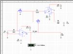
I'm using this circuit:
logarithmic_amplifier_circuit.PNG

But as you can see voltimeter value in my circuit is not the same like value in the transient simulation.

logarithmic_amplifier_output.PNG

I took this circuit from : **broken link removed**

Thank you very much in advance
 

It's a known standard cicruit, I've posted a link to similar circuits before. I see some possible problems with missing compensation capacitors. But you didn't tell which problems you observed in transient simulation. They can be at best guessed from the shown waveform.
 
The problem is that results from simulation Vout=-1.33 V with Vin=3 v don't match the results from the value (result from voltimeter) in the circuit which is -1.164 v
 

Presumed, you are using the same models in transient analysis, I can only imagine incorrect simulation setup. Without seeing all node voltages, I can't comment about possible reasons. If you are using a SPICE compatible simulator, you can also post the SPICE file. Or input file of a popular simulator like PSpice, LTSpice etc.
 
Status
Not open for further replies.

Similar threads

Part and Inventory Search

Welcome to EDABoard.com

Sponsor

Back
Top