Continue to Site

Welcome to EDAboard.com

Welcome to our site! EDAboard.com is an international Electronics Discussion Forum focused on EDA software, circuits, schematics, books, theory, papers, asic, pld, 8051, DSP, Network, RF, Analog Design, PCB, Service Manuals... and a whole lot more! To participate you need to register. Registration is free. Click here to register now.

12VDC to 24VDC flyback converter(multiple output)

Status
Not open for further replies.
hi murali_dece,

Thank you very much for helpful and useful advice.
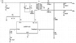
I just finish my assembly with all components and found out the output voltage is very unstable(voltage flow between 23.7VDC to 24.3VDC). I have make the change to input voltage became 12VDC 2A, so this is the main reason that can't generate stable output voltage?(since i need to generate 24VDC 1A instead 0.5mA).
what can i do to make the output voltage became stable(or maybe just change the capacitor from 560uF to 1200uF)?

please advice. Thank you.

final assembly.JPG
 
Hi peggy,
Can I ask the output voltage of both the supplies? And the load on both sides? And which package you are using of LM2577?
If TO220 package are you using any heat sink?
Please confirm the load on both supplies individually.
 
  • Like
Reactions: peggy

    peggy

    Points: 2
    Helpful Answer Positive Rating
hi Raza,
both output voltage are 24VDC 2A.I using LM2577S-ADJ and never use heat sink for my final assembly. or this is the root cause for can't generate stable output voltage?
 

Hi Peggy,
I had the same problem earlier but i found that output became stable after connecting the load(but that one is different Pulsewidth modulator). In your case you are using 35V output capacitor which is near to minimum requirement (at least greaterthan 20% Vout) go for higher value ex: 50V 1000uF.
Rc and Cc components also play a key role in output ripple stabilisation, slightly increase Cc value above 0.22uF and observe. i found one pot in your final assembly how you'r used that one and why.

with regards,
murali_dece
 
  • Like
Reactions: peggy

    peggy

    Points: 2
    Helpful Answer Positive Rating
Can you post a full schematic (a scanned hand sketch will do) so we can see what is going on and give some definitive answers please? We have quite a bit of experience with these step up IC's.
 
  • Like
Reactions: peggy

    peggy

    Points: 2
    Helpful Answer Positive Rating
Hi peggy,
Just one question, as you said the capacitors discharge one side quick and other slowly. Is this condition with load connected or off load?
As the these circuit must have always loaded otherwise their behavior will change once for all.
 
  • Like
Reactions: peggy

    peggy

    Points: 2
    Helpful Answer Positive Rating
sorry for late reply.
murali_dece,
I have change the capacitor to 50V 1000uF, the output voltage still same(unstable).The Cc value which i using is 0.47uF.The Pot is to adjust the output voltage. I already remove it since it just can adjust one output voltage.

orson cart,
attach are my schmetic diagram.

Raza,
I test the output voltage with off load.
 

Attachments

  • schematic.jpg
    schematic.jpg
    63.8 KB · Views: 90
The winding on D1 can conduct during the flyback period - but, the winding to D2 has the wrong phase and cannot conduct during the flyback period - the transformer needs changing so that there are two secondaries, each with the non-dot end going to the diode - Regards, Orson Cart.
 
  • Like
Reactions: peggy

    peggy

    Points: 2
    Helpful Answer Positive Rating
Hi Peggy,
I was gone through your final circuit, after comparing with similar circuits i felt diode 1N4148 in snubber circuit at primary side is too small to conduct scince our switching current is 3A max. I found 1N4937 diode in similar snubber circuit. I think stray inductance causing the problem. many times this will not be observed when load is connected. To avoid this condition during no load one more RC network is required parallel to output diode to discharge fly back currents. you may use 47ohm 1W resistor series with 1Kpf 63V capacitor across D1.
R C
---^v^v^v---||-----
----------| |---------
------|>|------------
D1
 
  • Like
Reactions: peggy

    peggy

    Points: 2
    Helpful Answer Positive Rating
HI peggy,
Can you give me the part number and brand name if possible of the transformer?
Enabling to look for proper connections in the secondary.
 
  • Like
Reactions: peggy

    peggy

    Points: 2
    Helpful Answer Positive Rating
Orson cart,
(the winding to D2 has the wrong phase and cannot conduct during the flyback period - the transformer needs changing so that there are two secondaries, each with the non-dot end going to the diode). You means all the D2 connecting are wrong? I not really understand what should change. Please advice.Thank you.

murali_dece,
attach are zoom in schematic diagram with new RC network. Please correct me if i draw wrongly.

Raza,
the flyback transformer is made by Myrra and part name is 74014.

Btw, I have found out about transformer, which output1 [pin7(S2) & pin 8(0V) are connect together] and output2 [pin9(S1) & pin 10(0V)connect together].if i connect both 0V to GND, thus means all 4 pins are shorted together. Should be connect like this or connect wrongly?

please advice. Thank you.
 

Attachments

  • edit.jpg
    edit.jpg
    46.3 KB · Views: 82
Hi peggay,
If you look at the transformer specifications of the transformer by Myrra in the attached table, the input is 140 volts.
Myrra.jpg
And here are the pin connections:
Myrra1.jpg
And here are the typical outputs of the transformer:
Myrra2.jpg
And here are the examples of the transformer usage:
Myrra3.jpg
Now if the input voltage is 140 volts you can not operate it on 12 volts. At the same time you need to connect the transformer windings in a proper manner, as shown in the attached diagram. Note the DOTTED ends, they mean the same polarity.
End_Conn.jpg
Hope it helps.
 
  • Like
Reactions: peggy

    peggy

    Points: 2
    Helpful Answer Positive Rating
Hi Peggy,
You have drawn correctly use similar RC network for both output diodes, In earlier posts i have suggeted to use aux winding (1&2) as primary and winding (drain 4 & +E 6) not to use. you have done the same thing or not. If yes what you have done to winding (drain 4 & +E 6) they left open or short circuited.
 
  • Like
Reactions: peggy

    peggy

    Points: 2
    Helpful Answer Positive Rating
raza,
I only able to found this flyback transformer and generate 24VDC output voltage.You have any recommendation or suggestion.

murali_dece,
u means i need draw the same RC network which i draw last time for both output diodes?For winding (drain 4 & +E 6), i left open and no connect to my board.
I only worry abou why all the output winding all connect together.(S1&0V short with S2&0V). because i just burnt one diode when i tesing and the output voltage reading is 42VDC..I wonder how come this happen.
Please advice.Thank you very much for helpful.
 

Hi Peggy,
I suggested RC net work across diode to provide discharge path to regenerative current occuring during switching pulse off time (stored magnetic flux collapses resulting current flow in opposite direction which does not pass through diode and pass through RC network if provided). If you are planning for dual output use two RC networks. dont short the output windings, your circuit is good enough to operate. to clarify your doubts regardinng secondary winding orientation, first don't make any common points for both outputs (no negative common for both o/p), connect the feedback network to (transformer output S1 or S2 any one dote end) and observe ouput voltage stability, now connect the feedback network to any one OV end which is of other end of previously tested O/P winding, again observe output voltage stability. Any one of above feedback mode solves your O/P instability problem then you can conclude problem lies in feed back, i.e feedback sample and PWM control circuitry are not on same phase. If you doesnot hear any audible noise from Transformer synchronous to output variation then your component selection and configuration is good only you need to fine tune.
Any of your friends are having Osscilloscope it is good aid to solve your problem.
 
  • Like
Reactions: peggy

    peggy

    Points: 2
    Helpful Answer Positive Rating
murali_dece,
Thank you very much for your reply.

If I use one RC networks for dual output,then all the output windings can shorted together?
You means both 0V(pin 8 &10) left open and no connect to GND pin?

connect the feedback network to (transformer output S1 or S2 any one dote end) and observe output voltage stability. After that, move to OV end which is of other end of previously tested O/P winding, again observe output voltage stability.

Then this will cause 2 scenario:
1)S1 connect to output diode & feedback network and 0V left open and no connect to GND pin. S2 connect to output diode and 0V left open and no connect to GND pin.
2)S1 connect to output diode and 0V connect to feedback network. S2 connect to output diode and 0V left open and no connect to GND pin.

Please advise me if i misunderstand your explanation.
 

Hello guyz!!!
I have studied in my schooling that energy can neither be created nor be destroyed...
then how the hell do you people try for 24V dc out of 12V without providing any external energy?
I think its impossible!!!
 

Hi peggy,
No, it does not happen short of two outputs if you use single RC network, not only bypassing the opposite currents RC network also protects the ouput diode from switching spikes. use RC network for both diodes.
you got my point but small correction from my side, scince in your circuit configuration there is no isolation for input and output atleast one output one end (0V) should be grounded for proper feedback, for clarity once again i will explain two scenarios

1) S1 should be connected to diode and feedbacck network and 0V of same winding to ground
2) now 0V of above winding connect to diode and feedback network and S1 to ground.
in both the above casses find which one gives good out put stabilization, regarding S2 and 0V left alone for ease of testing later you can deside how to connect.
if you dont achive stabilization you can try to isolate output by opto coupler.
Don't worry about your time and effort you can gain good knowledge and experience with this project.

---------- Post added at 18:20 ---------- Previous post was at 18:05 ----------

regarding srikath
Hi,
You are too young in electronics, you are correct energy never be created but it can be converted from one form to another. similarly we can raise the voltage by loosing current carrying capability and losses. V*I input=V*I output + losses
 
murali_dece,
Thank you for your suggestion.I follow your step and able to generate the stable output voltage. But i have met a problem that the output voltage will be increase till 28V DC when i using two multimeter to read the output. (able to read individual 24V DC output voltage by using one multimeter).

please advice. Thank you.
 

Dear peggy,
Congrats, please post your final circuit and respective taping points you have used for measurements for better understanding.
Regards,
Murali
 

Status
Not open for further replies.

Similar threads

Part and Inventory Search

Welcome to EDABoard.com

Sponsor

Back
Top