Continue to Site

Welcome to EDAboard.com

Welcome to our site! EDAboard.com is an international Electronics Discussion Forum focused on EDA software, circuits, schematics, books, theory, papers, asic, pld, 8051, DSP, Network, RF, Analog Design, PCB, Service Manuals... and a whole lot more! To participate you need to register. Registration is free. Click here to register now.

ferromagnetic transformer

Status
Not open for further replies.
I have nothing personal against you 'freeman2' but IMHO you have made a fundamental error about EM fields that has been disproved many times over the past hundred years. Look at the perfect or ideal transformer models. The net energy transfer to the magnetic field always increases as the resistance is reduced to zero (assuming no non-linear elements) . Increasing resistance in the coil increases the E field (voltage) energy. The product of these two fields will be the power wasted in the coil wiring. Trying to move the flux from the core into the wiring won't work unless you have something exotic like a Ferromagnetic superconductor.

File:Toroidal Transformer Poynting Vector.jpg - Wikipedia, the free encyclopedia
Transformer engineering: design and ... - Google Books
**broken link removed**
Ferromagnetic Superconductors
 
Last edited:
i agree this is not personal, you have just tactics. you dont even like me talking about the magnetic propertys of iron. i have asked you to stop posting, 4 more posts and you will have equalled what you have posted since joining in 2010 in just 1 week on this thread.

fvm the offer still stands, the ferromagnetic propertys of iron induce more current, i will post you iron wire at no cost to you.
i am working on a circuit diagram with info, but its the iron wire that induces more current. do you want me to send you the wire?
 

In my opinion, nsaspook has contributed valuable stuff about transformer operation.

I don't lack of different gauges of iron wire or transformer cores. But I don't see a purpose of assembling a test setup without a clear experimental problem.

Several contributions guessed about possible minor effects of a ferromagnetic wire on the magnetic circuit. I did an "survey" AC magnetic simulation with a ferrite rod setup and found field strength changes iron versus copper less then expected (a few percent). Although possible larger effects still won't imply extraordinary transformer properties, they could at least explain their appearance. But no results so far. That's why I'm asking for a reference design.
 
ok stay tuned i have put this back on the bench. i only need to put pics ect. together now

results still look odd.

the iron primary gives about 140mA out of the secondary, a identical copper gives around 60mA. the copper engages the current limit at about 1 amp. so it draws more current but gives less out, the transformer design is not like a mains as i will show. i have scope shots of the primary waveform, they look similar for copper and iron. if i am going wrong somewhere i can still not see how, copper wire should give around the same or more for a identical circuit with increased current considered.
 
Last edited:

Sounds strange. The questions from post #14 are still pending however.
 

putting this on the bench and doing a few tests shows some assumptions i have made are wrong you will see where i have gone wrong. iron wire looks to have some interesting propertys that i would like to know more about, here is a few findings and setup info, they are not in depth and extensive, there is only so much i can do.

the secondary is from another project and used only to save further winding and spool machining. it consists of 1.4mm width
cavitys 2mm apart machined into delrin plastic to about 12mm deep with a grove machined across so a continuous bifilar iron wire
can populate each cavity. it is then wired as tesla`s pancake coil patent. the secondary coil is only used to compare two
identical sized primary coils one being iron the other copper.

57_1315012553.jpg


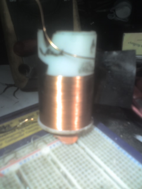
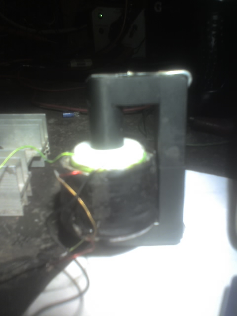
The transformer i have used has the secondary on the outside, primary in the middle and a empty spool on the inside.

example of a primary spool

82_1315012661.jpg


the primary and secondary wires must "face each other" that is wired over each other there can be a gap to allow for
spools, a magnetic connection through a core will not work and showed less current induced than the same copper primary. pure iron rather than iron alloy should give more.

for my test setup a psu with current limit of about 1 amp must be used.

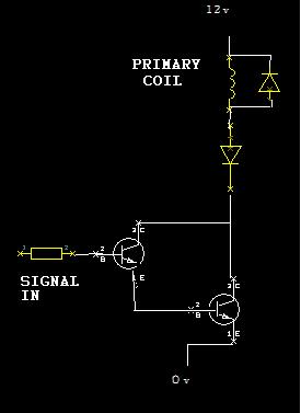
46_1315012826.jpg


the transistors are 2n3053 and 2n3055, diode across primary is fast recovery, all components picked out of spares box

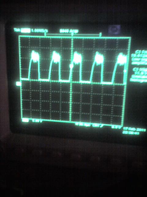
this is the primary waveform, both iron and copper give identical looking waveform

8_1315013263.jpg


comparison of iron and copper primary all readings taken from secondary through a diode.

iron gives 200mA short circuit at 1.5khz. 39v p-p open circuit scope test with more ramp shape out.

copper gives 86mA short circuit at 1.5khz. 3v p-p open circuit scope test with more pulse shape out.

at 10khz copper reads 1v p-p, iron reads 10v p-p current reading need to be re-done.

there is a strange effect, current flowing through the primary in one direction will give larger current and voltage
than the other direction with iron wire. thinking about this swapping the secondary wires may have the same affect, but i am guessing what is being viewed a second opinion is needed.

all tests are based on a identical transformer with only the primary wire metal being changed.
i believe the basic reason the primary coils give such different results is that copper atom has a neutral magnetic field while iron forms a magnetic dipole.
 
Last edited:

please also reveal the input (primary) current and voltage across coil for each of those measurements above.


The ferrite core your using looks like the core from a TV's hivoltage transformer for CRT, correct?
 

its back out into the workshop for that, scope shot is from collector referenced from ground.
i can take ac readings with a true rms meter for current reading, good enough?

voltage is 12v, shown on schematic, 5v/div on primary pic, the top has a lot of "ringing" with off pulse that shows up as a blur. copper wire engages current limit at about 1 amp, iron less current. you can adjust voltage/current drawn the results look to follow proportionally up to a point when the primary waveform goes fuzzy.

it`s a large (for modern standards) monitor flyback core. so yes

the copper primary draws more current than iron therefore should induce more current.
if the iron alloy gives a weaker magnetic field and has less current in the primary why does it induce more?

one thing it could be or is involved is both primary and secondary must be iron, magnetic flux from the primary aligns electrons in the secondary, so aligning there magnetic field which should aid the primary flux increaseing its strenght (go back to the physics links earlier if not sure what i am on about).
 
Last edited:

Some unclear points in my view:
- Load circuit at the secondary. You are talking about diodes.
- The term "bifilar" is possible source of misunderstandings. It's commonly used for a winding with no inductance, see Bifilar coil - Wikipedia, the free encyclopedia
Other possible meanings are primary and secondary wound together for maximal coupling or the tesla variant creating artificial windings capacitance.
- time scale of the waveform
- windings number of turns
 
the load on the secondary is either short circuit (current measurement) or open circuit (voltage measurement) through a single standard rectifier.

I have wound another spool for secondary with a "normal" coil, this will be checked as soon as i have time. it will be usefull to prove one way or the other affects of bifilar wound.

note there can be a gap between primary and secondary.

frequency used 1.5khz, 10khz and 14khz timebase is adjusted for viewing, could you be more specific as to what you are looking for here. for number of turns you will also need spool dimensions? i think more turns on the secondary will step up voltage.

question.

with the identical setup what do you think is causeing the difference in measurements.
 

Status
Not open for further replies.

Part and Inventory Search

Welcome to EDABoard.com

Sponsor

Back
Top