Continue to Site

Welcome to EDAboard.com

Welcome to our site! EDAboard.com is an international Electronics Discussion Forum focused on EDA software, circuits, schematics, books, theory, papers, asic, pld, 8051, DSP, Network, RF, Analog Design, PCB, Service Manuals... and a whole lot more! To participate you need to register. Registration is free. Click here to register now.

PIC controlling AC loads

Status
Not open for further replies.
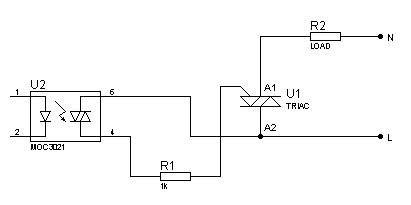
Thanks for pointing that out. I didn't know about the symbol. Anyways, the circuits above should work. :smile: I'll put up a fixed diagram.
 
Last edited:

Here's the fixed diagram:
54_1311182679.png
 

So in other words KerimF the symbol of the load Triac in post #5 should be flipped vertically. Is this correct?

Sure it is... any doubt? :-D

Now about the question... on which side the load is better to be placed... that depends on the installation.
In any case, the path of the trigger current is between MT2 (or A2) and the gate (when there is an optocoupler... and when a diac is used to build a simple dimmer).

Obviously in the direct control method, the triiger current is sent to the junction between G and MT1 (or A1). So MT1 would be connected to the positive or negative supply rail of the driving circuit. I usually connect MT1 to V+ (as 5V+) so that the triac driver can sink a current from the gate. Sourcing current into the gate is also possible but typically the sensitivity of triacs is lower in this case (hence more current will likely be needed).
 
Last edited:

Sure it is... any doubt? :-D

No doubt at all. I originally hadn't noticed it, but once you mentioned it on back on page #1, I saw that you were correct.

I'm busy with a project, so rather than read through three pages of debate, I thought I would get your summary at the end. :grin:

Thanks Again,

BigDog
 

very - 2 nice discussion of TRIAC .
what say all of u . TRIAC vs 2 ANTI PEARLER SCR ,
which is very good for inductive load (like inverter charging section & static relay for automatic stabilizers) ?
 

I think you meant... Triac vs bi-directional thyristor.

Triac has one gate, therefore it is relatively easy to trigger.
Bi-directional thyristor has two separate gates (electrically). The trigger is more complex because the gates are at different potentials (since one cathode is connected to the mains line, the other one to the load).

Using an opto triac, both gates can be triggered by one optocoupler via one resistor and two diodes (complete schematic could be found on datasheets). But at full power, some DC (average) current could exist (usually small) if the sensitivity of the two parallel thyristors is not the same (due to the different trigger delay near zero crossing).

Long ago, it was rather difficult to produce very high power triacs (both for high current and high voltage) as reliable as thyristors so there was the need to use bi-directional thyristors in the industrial machines.

My customers still asking me to design controllers to drive bi-directional thyristors (whick makes triggering much harder).
On the other hand, I noticed that very high power triacs (discrete or module) are widely available now. So I wonder why they still use thyristors! Perhaps there is a cost difference for high powers.

Kerim
 
Hi
I have made PID controller for the heater on msp430f2274.I wan to control the heating element by PWM.For that i have use the TRIAC.
Its possible to give the controller PWM to directly triac if no then why?Also told me why we are going to use triac driver circuit like moc3043?
Can I required the zero crossing circuit for the triac?If you know please told me.

Thanks in advance
Nilesh

please read from the first page it was explained there why we need the triac driver and need to detect the zero crossing before we can drive pwm to triac..
 
Hi
Triac using the ac supply and pwm is given by the dc supply so only for the protection purpose we are use opto isolater is it correct?I understand on 0 voltage we want to fire so we need to detect zero crossing point but for the heater i think don't need to detect the zero. can you explain in brief?


thanks in advance
nilesh
 

Triac using the ac supply and pwm is given by the dc supply so only for the protection purpose we are use opto isolater is it correct?

yes..


I understand on 0 voltage we want to fire so we need to detect zero crossing point but for the heater i think don't need to detect the zero. can you explain in brief?

the zero crossing point is for the triac not about the load, for us to control the triac via pwm... I dont know how to explain this clearly.. hehe lol
let's wait for the experts to reply.. :) hehehehe haha
 

this explains the use of opto coupler in some circuits
optoisolator ic
Sometimes the AC circuit tends draws very heavy current from your circuit. So associated sub-section of your circuit will get burnt, but not the micro-controller section, since most probably you would have isolated the digital signals from the driver analog ciruitry using opto-isolators.

---------- Post added at 18:07 ---------- Previous post was at 17:10 ----------

opto isolator, provide an output which can be used to fire the TRIAC if that's what you want it to do.

Be warned! The Opto Isolater does not fire at the zero point. It actually fires slightly after the zero point (or before depending which way you wire it!) since the LED in the opto isolator needs a forward voltage as well as enough current to emit photons to saturate the photo transistor on the other side.

Since this is the case you may need to adjust your CPU trigger circuit to wait for slightly less than a "full "or "half" cycle before trigerring the gate on the Triac. This is so that you can get it to fire the triac bang on the zero point (albeit a half or full cycle after the original zero crossing point). Do you care if it's a half or full cycle late ? Probably not!

A way to do this is to use the CPU to sample the time period between cycles. You can then do some math on where the actual triger point should be (by knowing about the original waveform) and adjusting your Triac firing pulse accordingly.

Eg, your Zero crossing detector actually triggers at 1.5 ms after the zero point. If you have a 60 Hz sine wave waveform (16.667 ms) you could choose to trigger your triac after (16.667 - 1.5ms) = 15.1667ms). You could also choose to trigger at (8.3333-1.5ms)=6.8333ms which would be bang on the half cycle.

Anonther thing to consider: AC is not necessarily the same period from cycle to cycle. The electricity companies guarantee the accuracy over a long time but it can drift quite a lot withing a small space of time. If you have a CPU, you could measure the time between "zero crossings" and make a psuedo PLL to predict what the period of the next cycle will be. This will also help you if don't want to have a lot of RF hash from switching an AC waveform in the wrong place.
 
Hi
Triac using the ac supply and pwm is given by the dc supply so only for the protection purpose we are use opto isolater is it correct?I understand on 0 voltage we want to fire so we need to detect zero crossing point but for the heater i think don't need to detect the zero. can you explain in brief?
nilesh

To control an AC load by a triac, there are two main methods:
(1)
Synchronous control in which the triac on/off follow the mains cycles.
(2)
Asynchronous control in which the triac is turned on at random (no need for a zero-cross detector). But the triac turns off when its output current reduces close to zero (below its holding current) and there is no gate driving current.

Obviously the second method is easier because the controller needs only to send a DC current to turn on the load or send continuous high frequency pulses as 15u/300us to save power. Then when the gate current is off, the triac will stay in its on state till its output current decreases below its holding current. This method is used when the on and off time periods are relatively long relative to mains cycle period mainly if the load is inductive in order to minimize the resulting DC average current at the AC side.

For the first synchronous method, there are two modes:
(A)
The triac is turned on only at the AC zero-crossing (actually close to it).
(B)
The triac is turned on anytime during the half cycle.

On the other hand, there are three topologies to drive the power triac gate:
(I)
Direct by the uC board.
(II)
By using an isolating transformer
(III)
By using an optocoupler with a triac output.

There are 2 types of triac optocoupler (topology III); one for (A) and another for (B).

The (III) for (A) doesn’t need a zero-cross detector for the uC since it is included in the optocoupler IC. So even if the start of the DC driving current (to the input LED) is made random, the opto triac will turn on close to the AC zero crossing only. This is good to regulate the temperature of heaters with minimum interference (EMI).

But (III) for (B) DOES need a zero-cross detector. This also applies for the topologies (I) and (II) as well.

Are there any comments so far? :-D
 
Last edited:

Hi
Thanks for your guidance. I have going to control the heating element by triac. I want to control only 1A current by the triac. As per above details its better to use only opto isolater without zero crossing circuit for me is it correct?Also told me some optoisolater need zero crossign circuit and some not can explain in brief.
Can you send me any schematic for that?
thank you

nilesh
 
Last edited:

If the heater control is dedicated to a professional electronic design, phase angle control methods would be excluded according to power quality regulations. Phase angle control is only permitted for lighting (dimmer) and appliances with speed controlled motors. Full wave switching is the appropriate method to comply with the regulations. You can either use slow pwm packet switching or switching of single full waves as a sigma-delta modulated pattern. The latter allows control of fast heaters, e.g. air heaters, without power pulsations.

Using a zero-crossing-detector opto-triac (MOC304x, MOC306x) would be the most simple way to achieve full wave switching. For slow pwm power control, it can be used without synchronization. Even the single wave switching can work without synchronization, if you generate an update rate near to the mains frequency, but you possibly get some incorrect switched waves due to the beat frequency.

The circuit for zero-crossing and non-zero-crossing triac control is effectively the same as shown in post #63. RC snubbers should be added to prevent self triggering with voltage transients.
 

Hi
can you tole me isit correct circuit for the heater coil control which is attched with this letter?
TRIAC_driver.jpg if i required zero crossing circuit then told me why or if not required then also told why?i want to control 1A of maximum current for the coil?
thank you
Nilesh
 
Last edited:

Status
Not open for further replies.

Part and Inventory Search

Welcome to EDABoard.com

Sponsor

Back
Top