Continue to Site

Welcome to EDAboard.com

Welcome to our site! EDAboard.com is an international Electronics Discussion Forum focused on EDA software, circuits, schematics, books, theory, papers, asic, pld, 8051, DSP, Network, RF, Analog Design, PCB, Service Manuals... and a whole lot more! To participate you need to register. Registration is free. Click here to register now.

help need to develop 3 mhz therapuetic ultrasound for physiotherapy

Status
Not open for further replies.

Senthilkumar_rjpm

Full Member level 2
Joined
Jul 21, 2009
Messages
123
Helped
15
Reputation
30
Reaction score
15
Trophy points
1,298
Location
chennai
Activity points
2,039
Hi all...
I am developing 3mhz ultrasound tharepy for my company...Already i developed the same machine in 1 MHZ frequency... (its nothing but to amplify 1 mhz frquency to 180v & give it to piezo electric crystal, It vibrate 1mhz frequency & its used for some treatments...) here we check that vibrate with water... If that water fountain is peak that freq (.8Mhz to 1.2Mhz) is typical for that crystal...


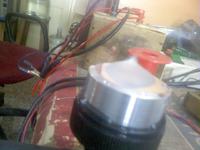
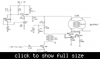
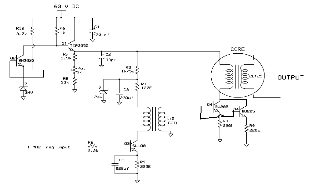
this 1mhz output amplifcation is acheived by this circuit


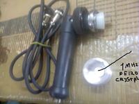
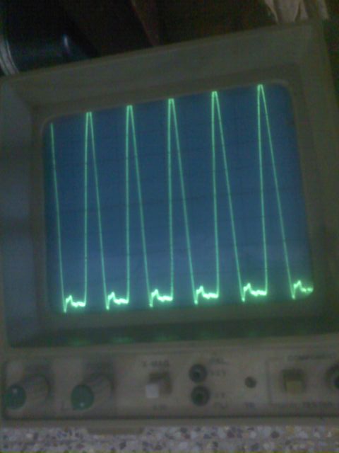
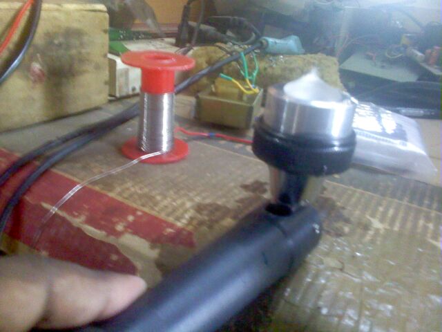
Piezo electric crystal & wave form are below (for 1 mhz)


56_1308738237.jpg


now.. iam developing the same in 3 mhz crystal.. initially i stuggled 3 mhz 180v amplification...
But now i amplify 3mhz to 120v using mosfet irf840 or irf 620 instead of transistor BU205 in above (amp) circuit....

if i give this (120v, 3mhz) to peizo crystal there is no fountain in water... (like 1 mhz).. (actully water fountain will come more sharper than 1 mhz but unfortunately i didnt get)

then i doubt in torroidal core same is using for 1 mhz.. My friends also suggest the same... (i didnt have much knowledge about this but i collect some details about this torroidal metrail form our supplier its HIZN, HF4)


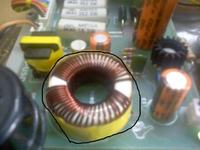
after that i change that torroid metterial & change turns of windings (to match impedence) etc... etc... but no improvement...

i am not able to find the solution for this problem for months... plz any one give some correct sollution or idea for this...
Thanks in advance...

---------- Post added at 16:17 ---------- Previous post was at 16:13 ----------

And also please anyone sugfgest me the best way or circuit to amplify 3mhz frequency 6v to 180v...
 

I imagine you might want a resonant power converter
kind of scheme, the big coil is not a problem if it's part
of a good power tank. What about RF LDMOS, they are
well above that frequency band so decently efficient.
Maybe resonant secondary and a ratioed primary to
let you use lower voltage devices.

If you look at DC-DC converters, integrated switch
ones past 10A can be had. Many will run off 6V.
So 30:1 turns ratio. The inductors I'm using at
1MHz are only maybe 6 turns. So can you make a
resonant secondary with about 100 turns, and
get a 3MHz natural ring with a good high-Q power
capacitor?
 
thanks for your reply sir.. but didnt have knowledge about resonant power conveter... & also how i make 100 (as primary secondary) turns in this small torriodal.. can u explain bit more thank you

---------- Post added at 17:44 ---------- Previous post was at 17:43 ----------

can someone please give me some solution?
 

Resonating with the piezo would definitely help, since you don't need to drive with such a high voltage.

Is this "water fountain" test really reliable? Maybe you just don't get the same effects due to the higher frequency, even if everything is working properly?
 

In my opinion, it's plausible that a transformer with a huge leakage inductance, that apparently works at 1 MHz must not necessarily be good for 3 MHz as well. I would however expect, that the generator is designed based on nominal or empirically determined transducer and other component parameters.

Regarding fountain test, it would be interesting to know the related output power level. I'm not sure if similar safety rules exist in India, but in Europe or the U.S., a medical ultrasonic source would undergo strict power level tests and the design has to gurantee, that the power level can't unintentionally increase due to technical faults.
 

First of all is the current through your PA increasing when you apply the 3MHz?. The 1:5 transformer might not be passing much (any?) 3MHz. I would make this a resonant circuit with the input capacity of your PA transistors, also the 2k2 series resistor would have a much more serious effect due to the input capacitance of the transistor. I would be very careful of the choice of ferrite for the output transformer, again I personally would make it air cored. You are building an amateur transmitter, try to get hold of the AARL handbook, this would help you loads (AARL = American Amateur Radio League). The closest amateur band is 3.5 MHz!!!
Frank
 

Resonating with the piezo would definitely help, since you don't need to drive with such a high voltage.

Is this "water fountain" test really reliable? Maybe you just don't get the same effects due to the higher frequency, even if everything is working properly?

Thanks mtweig...

Can you tell me more about RESONATING WITH THE PIEZO.. or refer me any totorials,book... & water foutain may not be correct method.. But as a small organisation its more cost to buy utrasonic test meter.. (our first machine was checked by that meter) with that reference we are doing this method for the past 20years more... its working...

The effect wise i saw the output (water fountain as sharp like pin) of 3mhz utrasound tharaphy in one impotred machine...

---------- Post added at 11:50 ---------- Previous post was at 11:44 ----------

In my opinion, it's plausible that a transformer with a huge leakage inductance, that apparently works at 1 MHz must not necessarily be good for 3 MHz as well. I would however expect, that the generator is designed based on nominal or empirically determined transducer and other component parameters.

Regarding fountain test, it would be interesting to know the related output power level. I'm not sure if similar safety rules exist in India, but in Europe or the U.S., a medical ultrasonic source would undergo strict power level tests and the design has to gurantee, that the power level can't unintentionally increase due to technical faults.

Thanks FvM sir....
I have saw some other company equipment sir... also using the same circuit for 1mhz & 3mhz... but that torroidal coil only different... They mould it & seal that coils...
Regarding fountain test as i told like above we hv doing this method for the several years...

---------- Post added at 11:59 ---------- Previous post was at 11:50 ----------

First of all is the current through your PA increasing when you apply the 3MHz?. The 1:5 transformer might not be passing much (any?) 3MHz. I would make this a resonant circuit with the input capacity of your PA transistors, also the 2k2 series resistor would have a much more serious effect due to the input capacitance of the transistor. I would be very careful of the choice of ferrite for the output transformer, again I personally would make it air cored. You are building an amateur transmitter, try to get hold of the AARL handbook, this would help you loads (AARL = American Amateur Radio League). The closest amateur band is 3.5 MHz!!!
Frank

Thanku chukey...
Please suggest me how to improve this circuit for 3mhz... (I got 120v Peak to Peak output with this same circuit in 3mhz, but i dont know how to measure or improve current in output).. or can you refer some alternate circuit... & Is this amateur transmitter? can you tell some more details about this...? thank you sir...
 

I suspect the "sharpness" of your "fountain" relates to the driver
waveform's match to the mechanical resonance of the piezo head.
Height may have to do with delivered power. Do you know what
conclusion to draw from shape attributes? I.e. do you have a
voltage problem or are you (say) running at 3.0MHz when the head
wants 3.2MHz?
 

Your transducer is like a capacitor with a large loss - this appears as a parallel resistor across it. Its the resistive bit that is actually doing the work. To tune out the capacitance just add series inductance untill the transducer appears resistive, or minimum impedance as you do this the current through your PA should rise. You can measure this by the vollt drop across your source resistor or the power supply consumption.
FWIW When I was involved with testing ultrasonic transducers, we had a home made set of balancing scales (made of brass!!)set in the testing tank and loaded with 50 grms. Applying the transducer head to the empty pan was meant to tip the scales the other way - bit more scientific then looking at water spouts.
Frank
 

I suspect the "sharpness" of your "fountain" relates to the driver
waveform's match to the mechanical resonance of the piezo head.
Height may have to do with delivered power. Do you know what
conclusion to draw from shape attributes? I.e. do you have a
voltage problem or are you (say) running at 3.0MHz when the head
wants 3.2MHz?

Thnk you dick..
normally here we consider shape is equal to power... so in fountain of water is peak that output power also peak... i dont have voltage problem becas here i see 120v peak yo peak while ampl... & also i have a variable frequency circuit fro 2.7mhz to 3.3mhz... so at any one of frequency it must tune with sharp water fountain... but i have a doubt with output current... but i dono how to measure it OR how to increase the output current in this circuit...???

---------- Post added at 16:12 ---------- Previous post was at 16:05 ----------

Your transducer is like a capacitor with a large loss - this appears as a parallel resistor across it. Its the resistive bit that is actually doing the work. To tune out the capacitance just add series inductance untill the transducer appears resistive, or minimum impedance as you do this the current through your PA should rise. You can measure this by the vollt drop across your source resistor or the power supply consumption.
FWIW When I was involved with testing ultrasonic transducers, we had a home made set of balancing scales (made of brass!!)set in the testing tank and loaded with 50 grms. Applying the transducer head to the empty pan was meant to tip the scales the other way - bit more scientific then looking at water spouts.
Frank

Thanks chukey....
Can i know how to increase the PA current in this circuit? and as u told can i add indictance (means take a copper & wind it roundly without core?)... & how i know this capacitance load(transducer) is come to resistive? can i measure it?
 

Thnk you dick..
Thanks chukey....
Can i know how to increase the PA current in this circuit? and as u told can i add indictance (means take a copper & wind it roundly without core?)... & how i know this capacitance load(transducer) is come to resistive? can i measure it?
Well to do it properly you should have some kind of network analyzer. I'm betting you don't have access to one, which makes your job difficult, but still doable. You'll just need a scope and a good sine wave generator.

This is basically an issue of impedance matching between your driver circuit and the piezo. The piezo is a pretty high impedance, which is why the step up transformer is there to transform it into a lower impedance as seen by the driver. However the transformer is not ideal, and its leakage inductance will also change the apparent complex impedance of the piezo. This can be good or bad, depending on what the leakage is. Ideally it will cancel out the capacitive impedance of the piezo, leaving only the resistive part, which is what you want. But in your case the leakage is probably too much, and it causing your piezo to look inductive, and is actually increasing its apparent impedance.

If you don't want to make a new transformer, then you can add capacitance to the primary side until it looks resistive again. To find its impedance, just connect a sine wave to it through a known source impedance, and simultaneously measure the source and load signals. By measuring their relative phase and amplitude, you can deduce the complex impedance of the load.
 
If you put a series resistor in the feed to the transducer (10 ohms?) put a signal diode bridge rectifier across it and hang a 0-1mA moving coil meter across the bridges DC output, you will have a crude RF current meter. If it reads more the FSD, reduce the resistor value (try a 100 ohm pot?). If you can't see a reading increase the resistor. Now you can add inductance in series and watch the current rise. As the Rf current rises the PA should start to draw more current. It is important that the PA input power should be at least 50W. 180 V across a 10K ohm impedance is not worth talking about ( V^2 / R = 1.44 W).
Frank
 
Hi all...
I am developing 3mhz ultrasound tharepy for my company...Already i developed the same machine in 1 MHZ frequency... (its nothing but to amplify 1 mhz frquency to 180v & give it to piezo electric crystal, It vibrate 1mhz frequency & its used for some treatments...) here we check that vibrate with water... If that water fountain is peak that freq (.8Mhz to 1.2Mhz) is typical for that crystal...

Hi Sir,

I am also trying to interface my 1 MHz ultrasonic transducer using your amplification circuit. I wanted to know whether we can use agilent frequency generator for getting the 1 MHz signal with maximum Vpp = 18.
Will this get amplified by sl108 transistor?
what is the voltage inputs of 1:5 transformer and the core of 22: 25?
How can I calculate it??
Kindly help me so that I can complete my final year project of underwater depth measurement.

Regards,
Rajeev
Coimbatore
 

Status
Not open for further replies.

Similar threads

Part and Inventory Search

Welcome to EDABoard.com

Sponsor

Back
Top